


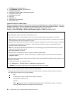
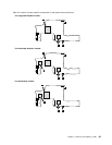
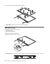
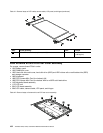

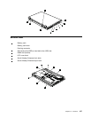


Table 41. Removal steps of LCD cable, camera cable, LCD panel, and hinges (continued)
9
9
9
9
10
10
Step Screw (quantity) Color
Torque
9
M2 × 3 mm, wafer-head, nylon-coated (4) Silver
0.181 Nm
(1.85 kgfcm)
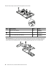
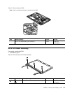
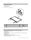
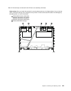
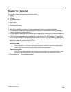
2050 Antenna kit and LCD rear cover assembly
For access, remove these FRUs in order:
• 1010 Battery pack
• 1030 DIMM slot cover
• 1050 Hard disk drive slot cover, hard disk drive (HDD) and HDD rubber rails or solid state drive (SSD)
and storage converter
• 1060 Keyboard
• 1080 PCI Express Mini Card for wireless LAN
• 1090 PCI Express Mini Card for wireless WAN or mSATA solid state drive
• 1100 Keyboard bezel assembly
• 1170 LCD unit
• 2010 LCD bezel assembly
• 2040 LCD cable, camera cable, LCD panel, and hinges
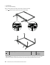
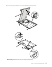
Table 42. Removal steps of antenna kit and LCD rear cover assembly
2
2
2
2
3
3
3
3
1
1
102 ThinkPad T520, T520i, and W520 Hardware Maintenance Manual