


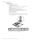
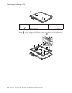

1210 System board, PC Card/ExpressCard slots assembly and
interposer card
Important notices for handling the system board
When handling the system board, bear the following in mind.
v At every point in the process, be sure not to drop or stack the system
board.
v The system board has an accelerometer, which can be broken by applying
several thousands of G-forces.
Note:
Dropping a system board from a height of as little as 6 inches so
that it falls flat on a hard bench can subject the accelerometer to as
much as 6,000 G’s of shock.
v Be careful not to drop the system board on a bench top that has a hard
surface, such as metal, wood, or composite.
v If a system board is dropped, you must test it, using PC-Doctor for DOS, to
make sure that the HDD Active Protection still functions (see below).
Note:
If the test shows that HDD Active Protection is not functioning, be
sure to document the drop in any reject report, and replace the
system board.
v Avoid rough handling of any kind.
v If you put a system board down, be sure to put it only on a padded
surface such as an ESD mat or conductive corrugated material.
After replacing the system board, run PC-Doctor for DOS to make sure that
HDD Active Protection still functions. The procedure is as follows:
1. Place the computer on a horizontal surface.
2. Run Diagnostics --> ThinkPad Devices --> HDD Active Protection Test.
Attention: Do not apply physical shock to the computer while the test is
running.
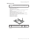
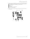
For access, remove these FRUs, in order:
v “1010 Battery pack” on page 63
v “1020 Ultrabay Slim device” on page 64
v “1030 Hard disk drive cover, hard disk drive, and hard disk drive rubber rails”
on page 65
v “1040 Palm rest or palm rest with fingerprint reader” on page 67
v “1050 DIMM” on page 74
v “1060 Keyboard” on page 75
v “1070 Modem daughter card (MDC-1.5)” on page 77
v “1080 PCI Express Mini Card for 802.11 a/b/g wireless LAN” on page 79
v “1100 PCI Express Mini Card for wireless WAN” on page 83
v “1120 Keyboard bezel and wireless WAN antenna cable (AUX)” on page 86
v “1130 Fan assembly” on page 89
v “1140 CPU” on page 93
v “1150 LCD assembly” on page 94
v “1160 Base cover” on page 98
v “1190 SIM card slot” on page 106
v “1200 Structure frame” on page 107
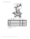
Removing and replacing a FRU
114 MT 1951, 1952, 1953, 1954, 1955, 1956, 2007, 2008, 2009, 2613, 2623, and 2637