


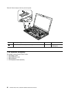
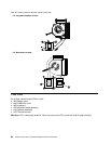
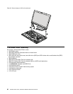
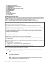
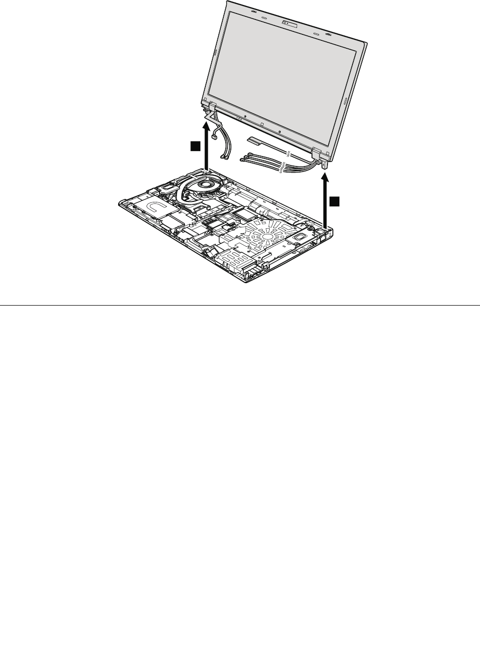
Table 32. Removal steps of LCD unit (continued)
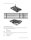
10
10
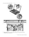
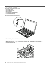
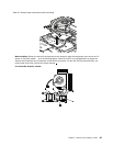
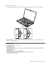
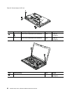
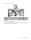
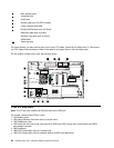
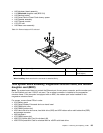
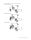
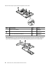
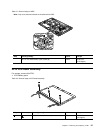
1180 Base cover assembly
For access, remove these FRUs in order:
• 1010 Battery pack
• 1020 Serial Ultrabay Enhanced device or travel bezel
• 1030 DIMM slot cover
• 1050 Hard disk drive slot cover, hard disk drive (HDD) and HDD rubber rails or solid state drive (SSD)
and storage converter
• 1060 Keyboard
• 1080 PCI Express Mini Card for wireless LAN
• 1090 PCI Express Mini Card for wireless WAN or mSATA solid state drive
• 1100 Keyboard bezel assembly
• 1110 Bluetooth daughter card (BDC-3.0)
• 1120 Backup battery
• 1130 Smart Card or Smart Card dummy spacer
• 1140 Speaker assembly
• 1150 Thermal module
• 1170 LCD unit
90 ThinkPad T520, T520i, and W520 Hardware Maintenance Manual