


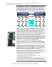
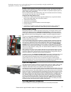
Leadership enterprise server with significantly lower cost of ownership in a highly available and
expandable, rack-dense, 2U dual-socket server
Please see the Legal Information section for important notices and information.
10
capability for future upgrades to Fibre Channel over Ethernet (FCoE) and iSCSI protocol offloads.
By using a common infrastructure for Ethernet and storage networks, data centers can reduce
capital expense (CapEx) for adapters, switches and cables, and operational expense (OpEx) for
power, cooling and IT administration.
End-to-end data protection with hardware parity, CRC, ECC and other advanced error checking
and correcting ensure that data is safe from corruption.
Integrated dual 10Gbps Ethernet ports:
• IPv4/IPv6 TCP, UDP checksum offload; Large Send Offload (LSO); Large Receive Offload;
Receive Side Scaling (RSS); IPV4 TCP Chimney Offload
• VLAN insertion and extraction
• Jumbo frames up to 9000 Bytes
• Preboot eXecutive Environment (PXE) 2.0 network boot support
• Interrupt coalescing
• Load balancing and failover support including adapter fault tolerance (AFT), switch fault
tolerance (SFT), adaptive load balancing (ALB), teaming support and IEEE 802.3ad.
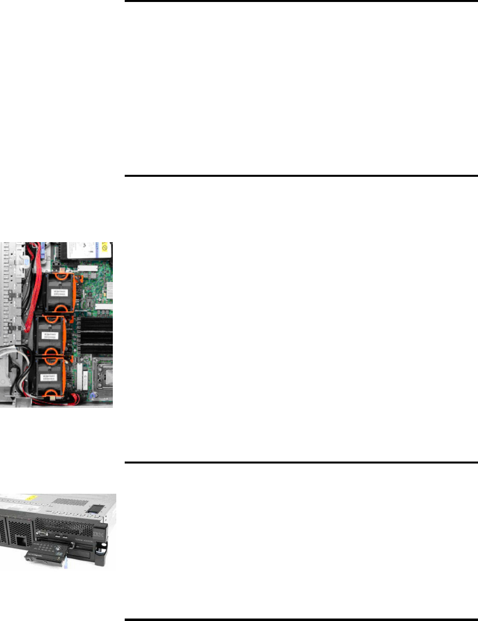
Ultra-Efficient Cooling
Strategically located fans, combined with efficient airflow paths, provide highly effective system
cooling for the x3650 M3, known as Calibrated Vectored Cooling. The base server with one
power supply includes 3 hot-swap fan modules, for redundant cooling. Each module includes 2
back-to-back fans with counter-rotating blades. In addition, each power supply also contains a
fan.
The system contains three cooling zones. Zone 1 (incorporating one fan module) cools all 18
DIMM sockets, Zone 2 (one fan module) cools the primary processor, and Zone 3 (one fan
module) cools the second processor.
The fans automatically adjust speeds in response to changing thermal requirements depending
on the zone and internal temperatures. When the temperature inside the server increases, the
fans speed up to maintain the proper ambient temperature. When the temperature returns to a
normal operating level, the fans return to their default speed. In addition, the Bosch BMP085
altimeter works in conjunction with IMM to govern fan rotation. At high altitudes the air is thinner
and doesn’t cool as well as at lower elevations. In most servers, the fans run fast all the time to
allow for use at high elevations, wasting power. The altimeter allows the IBM fans to run at lower
speeds at lower altitudes.
Why not simply run the fans at 100% capacity all the time? For several good reasons: to reduce
the ambient noise, reduce the wear-and-tear on the fans and reduce the server power draw. The
reduction in ambient noise and power draw may be relatively minor for a single server, but put
dozens or hundreds in a data center and it can make a big difference.
In addition, the server uses hexagonal ventilation holes in the chassis. Hexagonal holes can be
grouped more densely than round holes, providing greater airflow through the system cover.
This cooling scheme is important because newer, more powerful processors generate a
significant amount of heat, and heat must be controlled for the system to function properly.
There are temperature sensors on the planar placed to sense DIMM exhaust temperature, SAS
HDD exhaust temperature, and CPU2 exhaust temperature (through the altimeter).
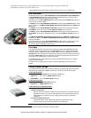
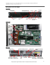
Light Path Diagnostics
Light path diagnostics enables a technician to quickly identify and locate a failed or failing system
component, such as a specific fan or memory DIMM. This enables quick replacement of the
component, which helps increase server uptime and lower operating costs.
The front of the server has an LED indicator light to show possible component failures. If the front
LED indicates an error condition, by pressing a button on the front of the server an LED panel will
pop out and drop down for easy viewing without the need to open the server cover or remove the
server from the rack. The light path diagnostics panel tells the servicer which component requires
attention. In addition, many components have their own identifying LEDs. For example, each of
the memory modules has an LED next to the socket, as do both processors, all adapter slots, all
fans, all power supplies, the voltage regulator module and the service processor, allowing the
servicer to easily identify exactly which component needs servicing. By following the “light path,”
the component can be replaced quickly, and without guesswork. (Note: In the event of a failed
DIMM, the system will restart and mark the DIMM as bad while offline, thus allowing the system
to continue running, with reduced memory capacity, until serviced.)
Hot-Swap/Redundant Components
System availability is maximized through the extensive use of hot-swap and redundant