


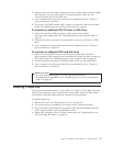

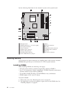
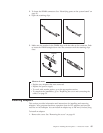
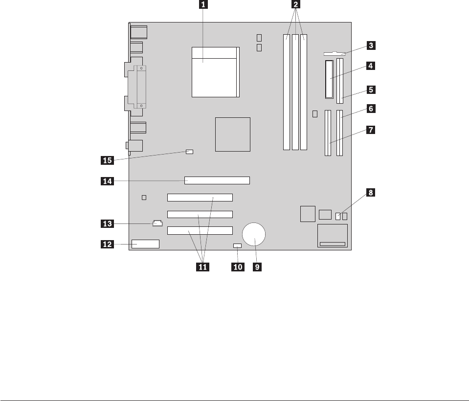
See the following illustration for the location of parts on the system board.
1 Microprocessor 9 Battery
2 DIMM connectors (1, 2, 3 left to right) 10SCSI LED connector
3 Front panel connector 11PCI slots
4 Power connector 12Front panel audio connector
5 Diskette drive connector 13CD-ROM audio connector
6 Primary IDE connector 14AGP slot
7 Secondary IDE connector 1512V Power connector
8 Clear CMOS/Recovery jumper
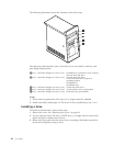
Installing memory
Your computer has three connectors for installing dual in-line memory modules
(DIMMs) that provide up to a maximum of 1.5 GB of system memory.
Installing DIMMs
When installing DIMMs, the following rules apply:
v Fill each system memory connector sequentially, starting at DIMM 1
v Use 3.3 V, synchronous, 168-pin, unbuffered, 133 MHz nonparity synchronous
dynamic random access memory (SDRAM)
v Use 64 MB, 128 MB, 256 MB, or 512 MB DIMMs in any combination
v DIMM heights of 38.1 mm (1.5 inches)
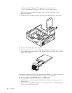
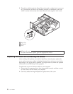
To install a DIMM:
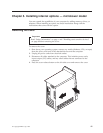
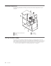
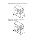
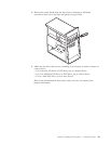
1. Remove the cover. See “Removing the cover” on page 41.
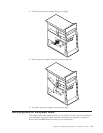
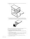
2. You might have to remove an adapter to gain access to the DIMM slots. See
“Installing adapters” on page 45.
44 User Guide