


I-8090 User Manual Version 1.0 06/2001
http://www.icpdas.com 1-6 ICPDAS
/SEL=0 (ZCTRL register), the high byte can be read out when set /SEL=1
(ZCTRL register).
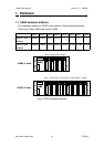
Register Add. R/W Bit 7 Bit 6 Bit 5 Bit 4 Bit 3 Bit 2 Bit 1 Bit 0
INDEX 0x04 R ZI YI XI
The index input C+/C- can read out from this register. These bits are active
high.
XI : indicate the index of X-axis (C+/C- input).
YI : indicate the index of Y-axis (C+/C- input).
ZI : indicate the index of Z-axis (C+/C- input).
Register Add. R/W Bit 7 Bit 6 Bit 5 Bit 4 Bit 3 Bit 2 Bit 1 Bit 0
XCTRL 0x00 W S1 S0 /RST /INH /SEL
YCTRL 0x01 W S1 S0 /RST /INH /SEL
ZCTRL 0x02 W S1 S0 /RST /INH /SEL
The XCTRL,YCTRL and ZCTRL register are control registers for X-axis, Y-
axis, Z-axis respectively.
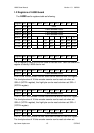
/RST
: reset counter to zero
/INH
: inhibit the counter data latch. This bit must be set 0 before read
out the counter value to inhibit the counter data latch to DATA
registers.
/SEL
: to select low byte or high byte for reading the counter value.
0 : low byte
1 : high byte
S1, S0
: to select counting mode
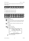
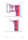
00
: quadrant counting mode
A
B
123456counter
Quadrant Counting Mode
Fig(2) Quadrant counting mode
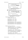
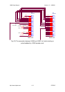
01
: CW/CCW counting mode