


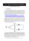

2. Hardware Installation
Users need to make a hardware connection between the CAN
devices before the application. The details of this are illustrated
below:
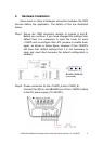
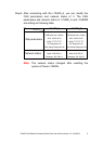
Step1
: Set-up the 120Ω terminator resistor of module A and B.
Before you continue, if you have changed the settings from
default then it is necessary to open the cover for each
i-7540D and re-configure their JP3 jumpers to enable them
again, as shown in below figure. However if the i-7540D’s
still have their default settings then it is not necessary to
open and reset them because the default configuration is
enabled.
Enable (default),
(Activate)
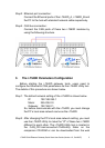
Step2: Power connection for the i-7540D_A and i-7540D_B.
Connect the (R)Vs+ and (B)GND pins of the i-7540D module
to the DC power supply (10~30VDC).
i-7540D CAN-Ethernet Gateway Quick Start User Guide (Version 1.2, Oct/2007)
2