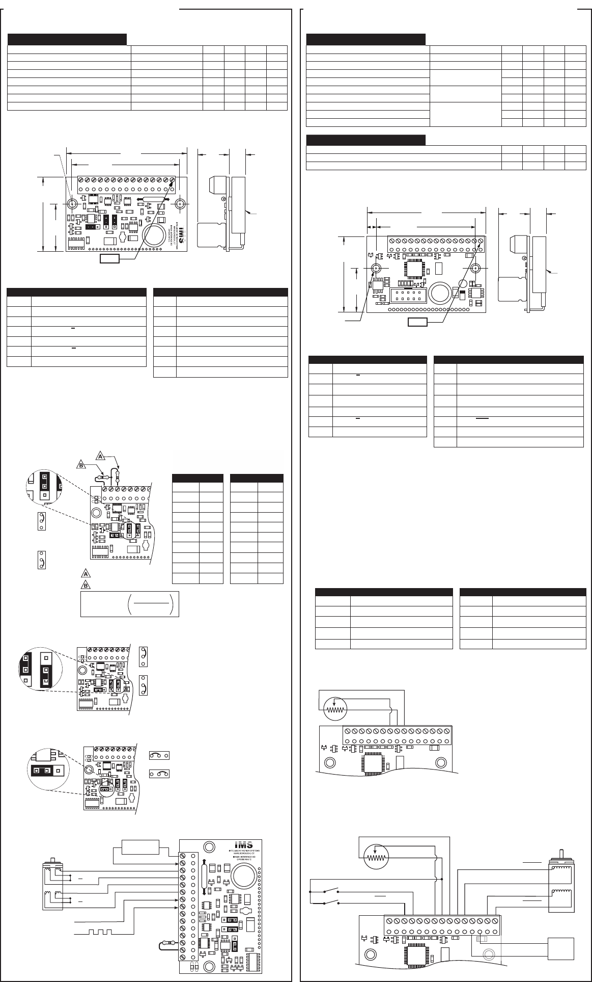
INT-462 Interface Board OSC-462H Variable Speed Control Board
Copyright © Intelligent Motion Systems, Inc.
General Specifications
Electrical Specifications Condition Min Typ Max Unit
Input Voltage Range — +12 — +48 VDC
Phase Output Current Per Phase 0.1 — 2 A
Quiescent Current (Driver Connected) Inputs/Outputs Floating — — 85 mA
Input Forward Current Isolated Inputs 8 10 12 mA
Input Forward Voltage Isolated Inputs 5 — 40 VDC
Signal Output Current Fault Output — — 25 mA
Drain-Source Voltage Fault Output — — 100 VDC
Drain-Source Resistance Fault Output — 6.5 — Ω
INT-462 Mechanical Specifications
Dimensions in Inches (mm)
PIN 1
2.550
(64.7)
2.120
(53.8)
0.985
(25.0)
1.569
(39.8)
2X Ø 0.150
(2X Ø 3.8)
0.670
(17.0)
0.343
(8.7)
Heatsink
Surface
INT-462 Pin Configuration
Pin # Function Pin # Function
1 Power Supply Return (Ground) 8 Step Clock Input (Isolated)
2 +V (+12 to +48 VDC) 9 +5 to +40 VDC Optocoupler Supply
3 Motor Phase A 10 Enable Input (Isolated)
4 Motor Phase A 11 Reset Input (Isolated)
5 Motor Phase B 12 Fault Output (Open-Collector)
6 Motor Phase B 13 Logic Ground
7 CW/CCW Direction Input (Isolated) 14 Current Adjustment
15 Current Reduction Adjustment
Mounting
Refer to the mounting instructions on the opposite side of this sheet or in the full
product manual Section 2.1.
Setting Run and Hold Output Current
A current adjustment resistor is REQUIRED.
I
I
I
I
R
RED
RUN
RUN
HOLD
HOLD
500 X
X
-
=
ENOFF/ENON
ENOFF/ENON
.
Current Adjust (See Table)
Reduction Adjust (See Equation)
ENOFF - Current Reduction
By Resistor
ENON - Outputs Disable
After a move
(0 Hold Current)
JP3 Settings
Current Adjustment Resistor
Values (Resistor Required)
I
Run
(A) 1% Ω I
Run
(A) 1% Ω
0.1 49 1.1 549
0.2 100 1.2 604
0.3 150 1.3 649
0.4 200 1.4 698
0.5 249 1.5 750
0.6 301 1.6 806
0.7 348 1.7 845
0.8 402 1.8 909
0.9 453 1.9 953
1.0 499 2.0 1000
Setting Half/Full Step Modes
Opto-Isolated Input Power Setup
OPTO/+5V
OPTO - Optos Powered by External
+5 to +24 VDC Supply (Sinking Inputs, Isolated)
+5V - Optos Powered by on-board +5V
(Sinking Inputs, Non-Isolated)
JP2 Settings
OPT
O/+5V
OPTO/+5V
F - Full Step Mode
H - Half Step Mode
JP1 Settings
F/H
F/H
Minimum Required Connections
Direction
+12 to +48
VDC Supply
Step Clock
ØA
ØB
ØB
ØA
ENOFF/ENON
PIN 1
OPTO/+5V
Jumper Settings
JP1: Full Step Mode
JP2: On-board +5V
JP3: Bridge Disable After Move
General Specifications
Electrical Specifications Condition Min Typ Max Unit
Input Voltage Range — +12 — +48 VDC
Phase Output Current Per Phase 0.1 — 2 A
Quiescent Current (Driver Connected) Inputs/Outputs Floating — — 85 mA
Low-Level Input Voltage
Stop/Start, DIR, SCLK
-0.5 — 1.5 VDC
High-Level Input Voltage 3.0 — 5.5 VDC
Low-Level Input Voltage
Enable Input Only
0.5 — 1.65 VDC
High-Level Input Voltage 3.85 — 5.5 mA
Output Drain-Source Voltage
Direction and Step
Clock Outputs
— — 80 V
Output Drain-Source Current — — 120 mA
Output Drain-Source On-Resistance — — 6 Ω
Speed Control Specifications Min Typ Max Unit
Speed Control Input Voltage 0 — +5 V
A/D Resolution — 10 — bit
Speed Control Potentiometer Resistance — 10 — kΩ
PIN 1
P3
P1
2.540
(64.5)
0.980
(23.9)
1.693
(43.0)
0.670
(17.0)
0.343
(8.7)
Heatsink
Surface
2X Ø 0.145
(2X Ø 3.7)
0.215
(5.40)
2.340
(49.40)
OSC-462H Mechanical Specifications
Dimensions in Inches (mm)
OSC-462H Pin Configuration
Pin # Function Pin # Function
1 Phase A Step Motor Output 8 Logic Ground (Potentiometer -)
2 Phase A Step Motor Output 9 Speed Control In (Potentiometer Wiper)
3
+V (+12 to +48 VDC)
10 Enable Input (HIGH, Disconnected=Enabled)
4
Power Supply Return (Ground)
11 Step Clock Input
5 Phase B Step Motor Output 12 Direction Input
6 Phase B Step Motor Output 13 Stop/Start Input
7 +5V Out (Potentiometer +) 14 Buffered Step Clock Output
15 Buffered Direction Output
Mounting
Refer to the mounting instructions on the opposite side of this sheet or in the full
product manual Section 2.2.
Parameter Setup
Parameter setup is accomplished in software using SPI (Serial Peripheral Interface)
IMS recommends the MD-CC300-000 USB to SPI converter/cable and the IMS
Motor Interface GUI to configure the parameters. This free software tool is on the
IMS CD and also available from the web at http://www.imshome.com. While the
available parameters are listed below, the device my be operated without changing the
parameters from the factory default.
The SPI Cable plugs into Connector P3, a 10-Pin IDC Style connector located on the
board.
Param Function Param Function
ACCL Acceleration MRC Motor Run Current
C Joystick Center RANGE Max/Initial Velocity Range
DB
Potentiometer/Joystick Deadband
STEP Half or Full Step Mode
FS
Potentiometer/Joystick Full Scale
VI Initial Velocity
MHC Motor Holding Current VM Max Velocity
Speed Control Connection
P1
9 8 7
Pin 7: +5 V Out
Pin 8: Speed Input
Pin 9: Logic GND
10 kΩ
The Analog Speed Control Input
may be connected on any device
with a 0 to +5 VDC output such as
a sensor
Minimum Required Connections
For connection of other Inputs/Outputs please refer to the IB462He product manual
Section 2.2.
Stepping Motor
Power Supply
P1
9 8 7 6 5 4 3 2 1
Pin 7: +5 V Out
Pin 6: Phase B
Pin 5: Phase B
Pin 2: Phase A
Pin 3: +V
Pin 4: GND
Pin 1: Phase A
Pin 8: Speed Input
Pin 9: Logic GND
Pin 9: Logic GND
Pin 13: Stop/Start
Pin 12: Direction
10 kΩ
+
-
13 12


