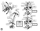
SEE FIGURE 3 FIGURE 3
C
Ceiling structure
Wood stud
Center of wood stud
D
E
C
B
A
Solid ceiling structure
E
D
C
C
B
A
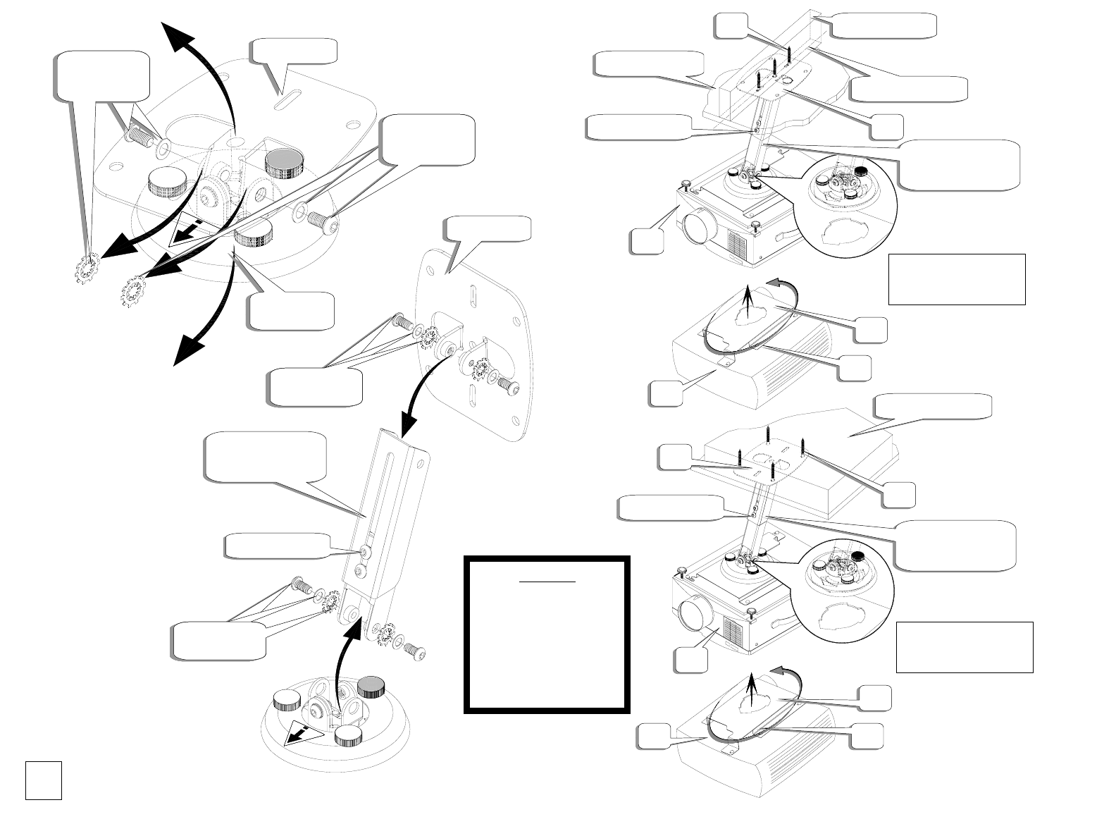
Optional
SP-LTMT-EXTP-S
extension ada
p
ter
Optional
SP-LTMT-EXTP-S
extension ada
p
ter
Ceiling plate
Mount
assembl
y
Remove
from mount
assembl
y
Remove
from mount
assembl
y
Remove
from mount
assembl
y
Remove
from mount
assembl
y
Ceiling plate
Replace the
hardware
Replace the
hardware
Optional
SP-LTMT-EXTP-S
extension ada
p
ter
Replace the
hardware
Replace the
hardware
Replace the
hardware
Insert and rotate 180°
and lock down
Insert and rotate 180°
and lock down
Replace the
hardware
Remove
from mount
assembl
y
Remove
from mount
assembl
y
Adjustable screws
Adjustable screws
Adjustable screws
WARNING
When using the optional
extension adapters and making
a height adjustment while
secured to the wall or ceiling do
not remove the screws
completely from the extension.
Failure to do so could result in
injury and damage to the
projector.
4


