


INSTALLATIONS
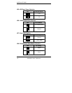
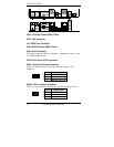
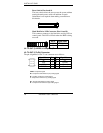
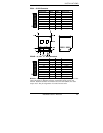
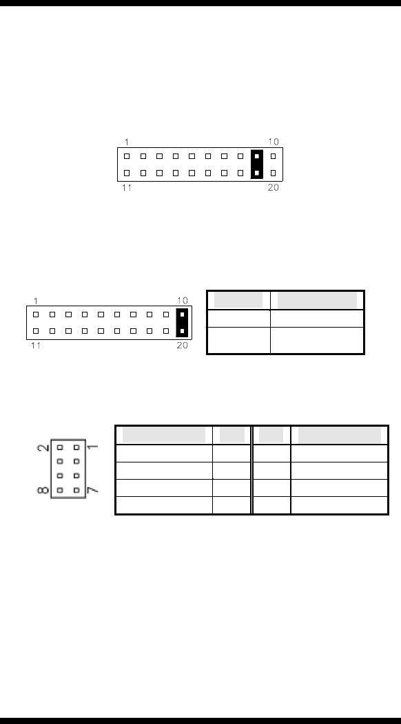
Reset Switch: Pins 9 and 19
The reset switch allows the user to reset the system without
turning the main power switch off and then on again.
Orientation is not required when making a connection to
this header.
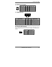
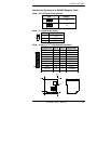
Hard Disk Drive LED Connector: Pins 10 and 20
This connector connects to the hard drive activity LED on
control panel. This LED will flash when the HDD is being
accessed.
Pin # Signal Name
10 HDD Active
20 5V
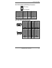
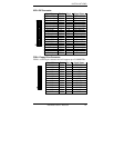
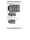
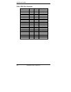
J4: TV-OUT (S-VIDEO & Composite) Connector
J5: TV-OUT (Y,Pr,Pb) Connector
The pin assignments of the TV out connector are as follows:
Signal Name Pin Pin Signal Name
NC 1 2 NC
SL/Y 3 4 Ground
SC/Pr 5 6 Ground
CVBS/Pb 7 8 Ground
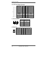
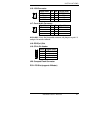
CVBS :
Co mposite signal
Pb :
Component Chrominance (Pb) analog signal
SL :
S-Video Luminance analog signal
Y :
Component Luminance (Y) analog signal
SC :
S-Video Chrominance analog signal
Pr :
Component Chrominance (Pr) analog signal
18 2804080 User’s Manual