


5 Chapter 1
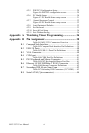
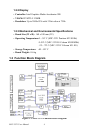
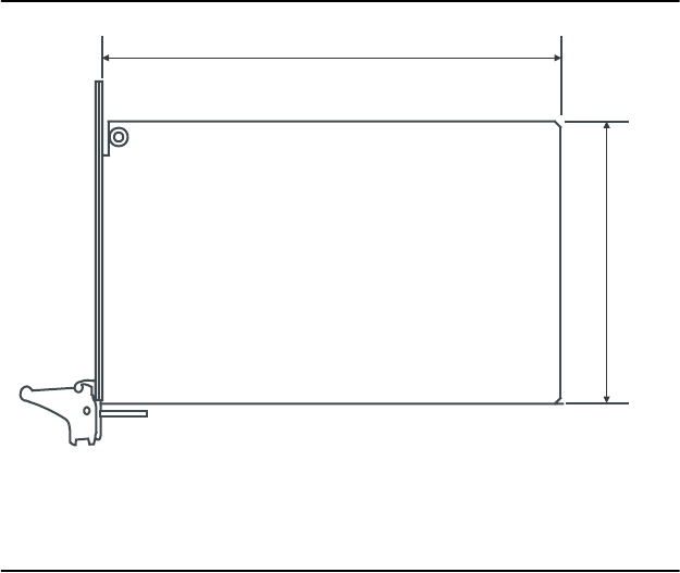
1.4 Board Dimensions
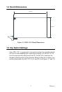
Figure 1.2: MIC-3321 Board Dimensions
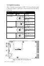
1.5 Dip Switch Settings
Since MIC-3321 is composed of one main board and one daughter board,
for ease of understanding and a convenient naming, we will use 1F (1st
level) to represent the main board, and 2F (2nd level) to represent the
daughter board hereafter in this manual. Before setting the switches, you
need to disassemble the MIC-3321 to 1F and 2F as in Figures 1.3 and 1.4.
160 mm
100 mm