2
1
3
5
7
9
11
1
3
15
17
19
2
1
2
4
6
8
10
12
14
16
1
8
20 22
L
ink\A
c
tivi
ty
Lin
k = So
lid G
ree
n
Ac
t
ivity = Blink
ing
Gre
en
P
o
r
t
1
P
o
r
t
2
1
2
3
4
5
6
7
8
9
1
0
1
1
12
1
3
1
4
15
16
17
18
19
2
0
21
22
1
0
/
1
0
0
B
a
s
e
-
T
M
o
d
u
l
e
P
o
r
t
1
P
o
r
t
2
S
w
it
c
h
S
t
a
t
u
s
S
t
a
t
u
s
L
i
n
k
S
tackin
g
Mo
d
ul
e
Mo
d
ul
e
A
M
o
du
le
A
In
te
l
®
E
x
p
re
s
s
5
3
5
T
S
w
itc
h
Quick Start
2
Install the Switch
Rack: Use the three small screws to
attach the brackets to the switch.
Shelf: Peel off the protective
backing and attach the rubber
feet to the switch.
1
• Remove the switch and parts from the box.
• Attach the enclosed brackets if you plan
to mount the switch in a rack.
• Install the Intel
®
Express 535T Switch in a
rack or on a shelf.
• Plug in the power cord.
Figure 1: Install the Switch
Check the
Connections
• Check the port LEDs to confirm the link
status.
• A solid green LED indicates a valid link.
Port LED (Green)
Solid Green = Link
Blinking Green = Activity
3
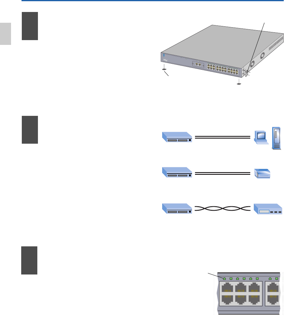
Connect
the Devices
10/100
Switch Hub or Switch
Switch Print Server
Switch PC/Server
straight-through
From To
crossover
Figure 2: Connect the Devices
Figure 3: Check the Connections
straight-through
• All ports automatically detect the speed
and duplex-mode of any connected
device.
• Connect PCs and print servers to the
switch with straight-through cables.
• Use a crossover cable to connect a switch
to another switch or hub.
• Use only CAT 5 UTP cable to connect
100Mbps devices. To connect 10Mbps
devices, use CAT 3, 4, or 5 UTP cable.
English


