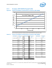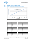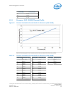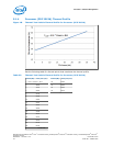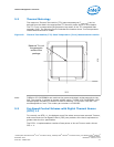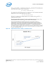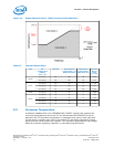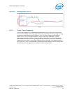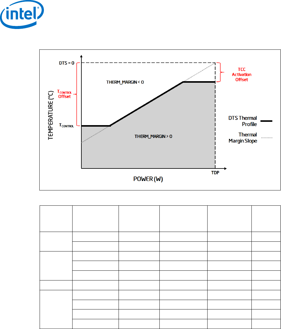
Figure 21. Digital Thermal Sensor (DTS) Thermal Profile Definition
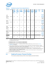
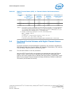
Table 27. Thermal Margin Slope
PCG Die
Configuration
(Native)
Core + GT
TDP (W) TCC Activation
Temperature (°C)
MSR 1A2h 23:16
Temperature
Control Offset
MSR 1A2h 15:8
Thermal
Margin
Slope
(°C / W)
2013D
4+2 (4+2) 84 100 20 0.654
4+0 (4+2) 82 100 20 0.671
2013C
4+2 (4+2) 65 92 6 0.722
2+2 (2+2) 54 100 20 1.031
2+1 (2+2) 53 100 20 1.051
2013B 4+2 (4+2) 45 85 6 0.806
2013A
4+2 (4+2) 35 75 6 0.806
2+2 (4+2) 35 85 6 1.016
2+2 (2+2) 35 85 6 1.021
2+1 (2+2) 35 90 6 1.141
Processor Temperature
A software readable field in the TEMPERATURE_TARGET register that contains the
minimum temperature at which the TCC will be activated and PROCHOT# will be
asserted. The TCC activation temperature is calibrated on a part-by-part basis and
normal factory variation may result in the actual TCC activation temperature being
higher than the value listed in the register. TCC activation temperatures may change
based on processor stepping, frequency or manufacturing efficiencies.
5.5
Processor—Thermal Management
Desktop 4th Generation Intel
®
Core
™
Processor Family, Desktop Intel
®
Pentium
®
Processor Family, and Desktop Intel
®
Celeron
®
Processor Family
Datasheet – Volume 1 of 2 December 2013
74 Order No.: 328897-004


