


Contents
vii
5 Desktop Board Resources
Memory Map .........................................................................................................................71
DMA Channels......................................................................................................................71
Interrupts...............................................................................................................................72
A Error Messages and Indicators
BIOS Beep Codes.................................................................................................................73
BIOS Error Messages ...........................................................................................................74
B Regulatory Compliance
Safety Regulations................................................................................................................77
European Union Declaration of Conformity Statement .........................................................77
Product Ecology Statements................................................................................................. 78
EMC Regulations ..................................................................................................................79
Product Certification Markings (Board Level)........................................................................ 80
Figures
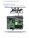
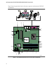
1. Desktop Boards D915GAV and D915GEV Components ............................................... 12
2. Intel Desktop Boards D915GUX and D915GAG Components.......................................14
3. Back Panel LAN Connector LED Locations ...................................................................20
4. Location of Standby Power Indicator..............................................................................25
5. Installing the I/O Shield...................................................................................................30
6. Desktop Boards D915GEV and D915GAV Mounting Screw Hole Locations .................31
7. Lift Socket Lever.............................................................................................................32
8. Lift the Load Plate and Don’t Touch the Socket Contacts.............................................. 32
9. Remove the Protective Socket Cover.............................................................................33
10. Remove the Processor from the Protective Processor Cover/Do Not Touch.................33
11. Install Processor............................................................................................................. 34
12. Close the Load Plate ......................................................................................................34
13. Connecting the Processor Fan Heat Sink Cable to the Processor Fan Connector ........35
14. Dual Configuration Example 1........................................................................................36
15. Dual Configuration Example 2........................................................................................37
16. Dual Configuration Example 3........................................................................................37
17. Matching the Correct DIMM............................................................................................ 38
18. Installing a DIMM............................................................................................................ 39
19. Inserting the PCI Express x16 Card and Covering the Back Panel VGA Port ...............41
20. Connecting the IDE Cable ..............................................................................................42
21. Connecting the Serial ATA Cable...................................................................................43
22. Internal Headers.............................................................................................................44
23. Back Panel Audio Connectors for Flexible 6-Channel Audio System ............................47
24. Location of Fan Headers ................................................................................................48
25. Connecting 2x10 Power Supply Cables ......................................................................... 49
26. Connecting 2x12 Power Supply Cables ......................................................................... 50
27. Location of the PCI Bus and PCI Express Add-in Card, and Peripheral Interface
Connectors for Desktop Boards D915GAV and D915GEV ............................................51
28. Location of the BIOS Configuration Jumper Block ......................................................... 52
29. Back Panel Connectors..................................................................................................54
30. Removing the Battery .....................................................................................................58