


INSTALLATIONS
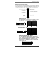
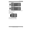
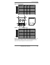
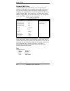
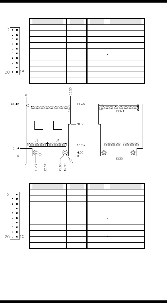
ID391 J2 DVI Connector
Signal Na me Pin # Pin # Signal Name
TDC 1- 2 1 TDC1+
Grou nd 4 3 Ground
TLC- 6 5 TLC+
+5V 8 7 Ground
NC 10 9 HPDET
TDC 2- 12 11 TDC 2+
Grou nd 14 13 Grou nd
TDC 0- 16 15 TDC 0+
NC 18 17 NC
DD C_S C 20 19 DD C_S D
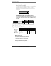
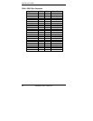
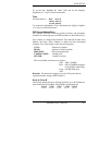
ID391D J1, J2 1
st
/2
nd
DVI Connectors
Signal Na me Pin # Pin # Signal Name
TDC 1- 2 1 TDC1+
Grou nd 4 3 Ground
TLC- 6 5 TLC+
+5V 8 7 Ground
NC 10 9 HPDET
TDC 2- 12 11 TDC 2+
Grou nd 14 13 Grou nd
TDC 0- 16 15 TDC 0+
NC 18 17 NC
DD C_S C 20 19 DD C_S D
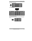
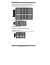
Remarks: When using dual DVI, the first DVI video output is through J1. After
setting the drivers in Windows, then the second DVI output (via J2) will
function. ID391D and ID391 are different since the latter (ID391) has video
output via J2. The pin assignments of J1 and J2 are the same.
2804080 User’s Manual 25