


13
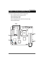
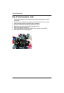
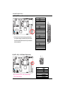
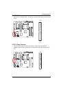
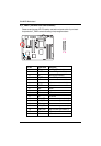
Hardware Installation Process
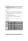
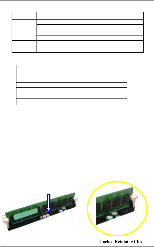
Table 1. Supported DIMM Module Type
Table 2. DIMM Placement DDR2-533/667
Technology Organization SDRAM Chips/DIMM
256MB 8MB x 8 x 4 bks 8
16MB x 4 x 4bks 16
512MB 16MB x 8 x 4bks 8
32MB x 4 x 4bks 16
1GB 32MB x 8 x 4bks 8
64MB x 4 x 4bks 16
DIMM Configuration DIMM1 DIMM2
1 Single Rank Empty Empty
1 Dual Rank Empty Empty
2 Single Rank Empty Single Rank
1 Dual Rank, 1 Single Rank Empty Single Rank
2 Dual Rank Empty Dual Rank
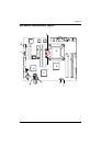
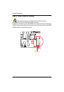
Installation Steps:
1. Unlock a DIMM socket by pressing the retaining clips outwards.
2. Aling a DIMM on the socket such that the notch on the DIMM exactly match the notches in the
socket.
3. Firmly insert the DIMMinto the socket until the retaining clips snap back in place.
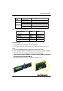
4. When installing the DIMM into the DIMM socket, we recommend to populate one DIMM in
Channel A module and one in Channel B module for best performance.
Please note that each logical DIMM must be made of two identical DIMMs having the same
device size on each and the same DIMM size.
5. Reverse the installation steps when you wish to remove the DIMM module.