


Hardware Installation- 23 -
English
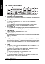
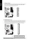
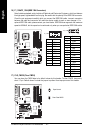
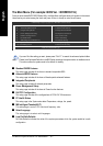
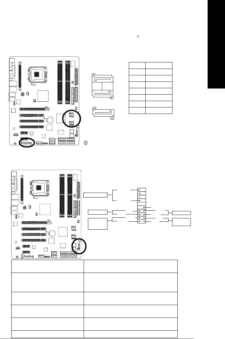
11) F_PANEL (Front Panel Jumper)
Please connect the power LED, PC speaker, reset switch and power switch etc of your chassis front
panel to the F_PANEL connector according to the pin assignment below.
HD (IDE Hard Disk Active LED) (Blue) Pin 1: LED anode(+)
Pin 2: LED cathode(-)
SPEAK (Speaker Connector) (Amber) Pin 1: Power
Pin 2- Pin 3: NC
Pin 4: Data(-)
RES (Reset Switch)(Green) Open: Normal
Close: Reset Hardware System
PW (Power Switch) (Red) Open: Normal
Close: Power On/Off
MSG(Message LED/Power/Sleep LED) Pin 1: LED anode(+)
(Yellow) Pin 2: LED cathode(-)
NC ( Purple) NC
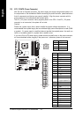
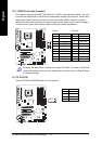
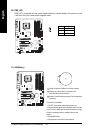
Pin No. Definition
1 GND
2 TXP
3 TXN
4 GND
5 RXN
6 RXP
7 GND
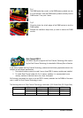
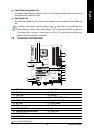
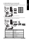
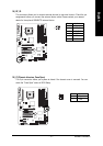
9) SATAII0/1/2/3 (SATA 3Gb/s Connectors, Controlled by ICH7R)
10) ESATAII0/1 (SATA 3Gb/s Connectors, Controlled by Sil3132)
SATA 3Gb/s can provide up to 300MB/s transfer rate. Please refer to the BIOS setting for the SATA
3Gb/s and install the proper driver in order to work properly.
1
7
12
19
20
HD-
HD+
RES+
RES-
NC
SPEAK-
MSG-
MSG+
PW-
PW+
SPEAK+
Message LED/
Power/
Sleep LED
Power Switch
Speaker Connector
IDE Hard Disk
Active LED
Reset Switch
(controlled by ICH7R)
(controlled by Sil3132)
17
71
Only for GA-8I955X Royal.