


HS-872P User’s Manual Hardware Setup
Switch and Indicator
36
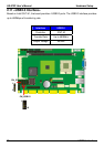
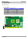
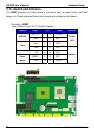
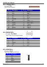
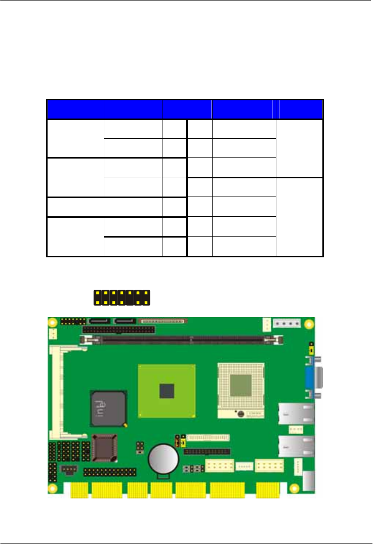
2.15 <Switch and Indicator>
The JFRNT provides front control panel of the board, such as power button, reset and
beeper, etc. Please check well before you connecting the cables on the chassis.
Connector: JFRNT
Type: onboard 14-pin (2 x 7) 2.54-pitch header
Function Signal PIN Signal Function
Vcc (+) 1 2 (+) Vcc
IDE LED
Active 3 4 N/C
Reset 5 6 GND
Power
LED
Reset
GND 7 8 Vcc
N/C 9 10 N/C
PWRBT 11 12 N/C
Power
Button
GND 13 14 SPKIN
Speaker
1
14
JFRNT