


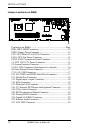
INSTALLATIONS
16 IB868 User’s Manual
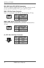
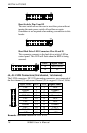
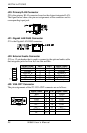
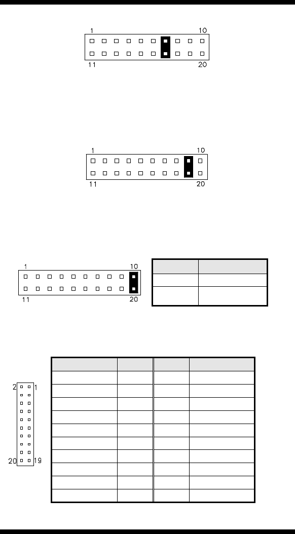
Reset Switch: Pins 9 and 19
The reset switch allows the user to reset the system without
turning the main power switch off and then on again.
Orientation is not required when making a connection to this
header.
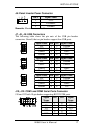
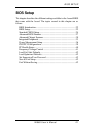
Hard Disk Drive LED Connector: Pins 10 and 20
This connector connects to the hard drive activity LED on
control panel. This LED will flash when the HDD is being
accessed.
Pin # Signal Name
10 HDD Active
20 5V
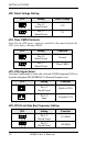
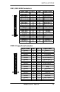
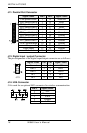
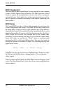
J4, J5: LVDS Connectors (2nd channel, 1st channel)
The LVDS connectors, DF13 20-pin mating connectors, are composed of
the first channel (J5) and second channel (J4) to support 18-bit or 36-bit.
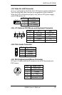
Signal Name Pin # Pin #
Signal Name
TX0- 2 1 TX0+
Ground 4 3 Ground
TX1- 6 5 TX1+
5V/3.3V 8 7 Ground
TX3- 10 9 TX3+
TX2- 12 11 TX2+
Ground 14 13 Ground
TXC- 16 15 TXC+
5V/3.3V 18 17 ENABKL
+12V 20 19 +12V
Remarks: Maximum current for +12V is 1A.