


INSTALLATIONS
IB865 User’s Manual 13
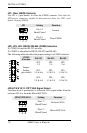
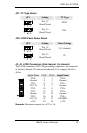
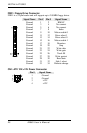
JP1: TV Type Select
JP1 Setting TV Type
Pin 1-2
Short/Closed
NTSC
Pin 2-3
Short/Closed
PAL
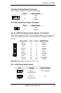
JP2: LVDS Panel Power Select
JP2 Setting Panel Voltage
Pin 1-2
Short/Closed
3.3V (default)
Pin 2-3
Short/Closed
5V
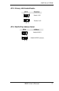
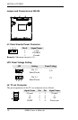
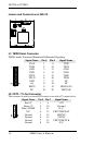
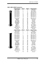
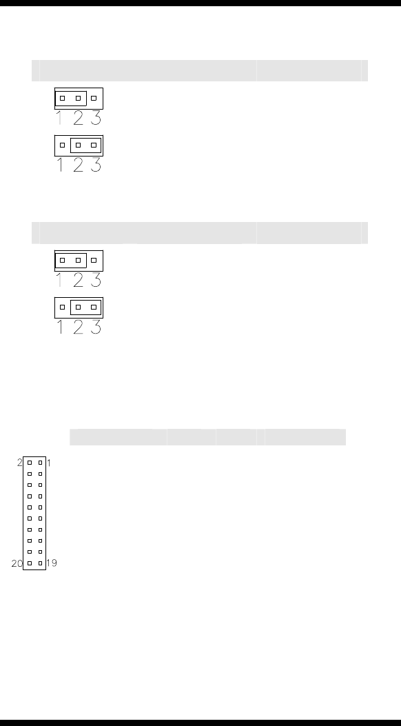
J2, J3: LVDS Connectors (2nd channel, 1st channel)
The LVDS connectors, DF13 20-pin mating connectors, are composed
of the first channel (J2) and second channel (J3) to support 24-bit or
48-bit.
Signal Name Pin # Pin #
Signal Name
TX0- 2 1 TX0+
Ground 4 3 Ground
TX1- 6 5 TX1+
5V/3.3V 8 7 Ground
TX3- 10 9 TX3+
TX2- 12 11 TX2+
Ground 14 13 Ground
TXC- 16 15 TXC+
5V/3.3V 18 17 ENABKL
+12V 20 19 +12V
Remarks: Maximum current for +12V is 1A.