


Demo Board for 10/100 and 100BASE-FX Applications — LXD970A
Development Kit Manual 7
2.0 Equipment and Setup
The LXD970A Demo Board includes all the components needed for a successful evaluation.
However, the following additional equipment is recommended:
• NetCom System X-1000 transceiver test box configured with firmware version 1.17 or newer.
• PC with Fast Ether Windows (version 1.5 or newer) installed.
• Various lengths of Category 5 Unshielded Twisted-Pair (UTP) cable (1, 20, 40, 60, 80, 100,
120 and 140 meters).
• For 100BASE-FX evaluation, a fiber-optic transceiver module (HFBR-5103) and fiber-optic
cable are required.
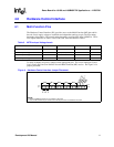
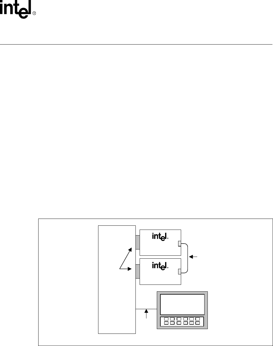
2.1 Test Setup
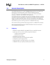
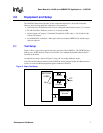
Figure 1 shows a typical test setup for the basic operation of the LXD970A. The LXD970A plugs
directly into a X1000 NetCom Transceiver Test Box via a standard 40-pin MII connector that is
included on the board.
An optional test setup is shown in Figure 2 using a PC for testing additional nodes.
Note: JP3 and JP4 must be installed on the LXD970A for the Netcom System X-1000 transceiver
test box to access the MII management registers inside the LXT970A.
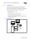
Figure 2. Basic Test Setup
NETCOM
X1000
LXD970A
LXD970A
UTP
Loop
MII
FAST ETHER
Windows
RS232
PC