


INSTALLATIONS
8 MI920 User’s Manual
Setting the Jumpers
Jumpers are used on MI920 to select various settings and features
according to your needs and applications. Contact your supplier if you
have doubts about the best configuration for your needs. The following
lists the connectors on MI920 and their respective functions.
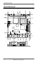
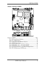
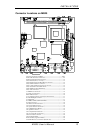
Jumper Locations on MI920 ........................................................... 9
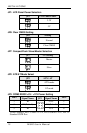
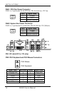
JP1: LCD Panel Power Selection.................................................. 10
JP8: Clear CMOS Setting ............................................................. 10
JP7: CompactFlash Slave/Master Selection .................................. 10
JP2: ATX/AT Mode Select ........................................................... 10
JP3: COM3 RS232 +5V / +12V Power Setting ............................ 10
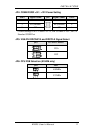
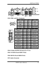
JP4: COM4 RS232 +5V / +12V Power Setting ............................ 11
[JP5: VGA/DVI DDCDATA and DDCCLK Signal Select ........... 11
JP6: CPU FSB Selection (915GM only) ....................................... 11