


INSTALLATIONS
12 MB865 User’s Manual
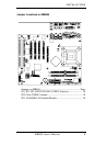
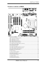
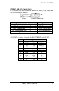
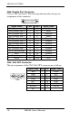
Connectors on MB865
The connectors on MB865 allows you to connect external devices such
as keyboard, floppy disk drives, hard disk drives, printers, etc. The
following table lists the connectors on MB865 and their respective
functions.
Connector Locations on MB865...................................................13
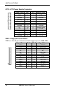
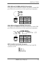
ATX1: ATX Power Supply Connector......................................... 14
FDD1: Floppy Drive Connector................................................... 14
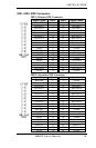
IDE1, IDE2: EIDE Connectors.....................................................15
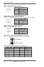
FAN1: CPU Fan Power Connector............................................... 16
FAN2: Chassis Fan Power Connector ..........................................16
FAN3: System Fan Power Connector...........................................16
CN1: PS/2 Keyboard and PS/2 Mouse Connectors......................16
CN2, J1, J10, J13: Serial Ports .....................................................17
CN3: Parallel Port Connector .......................................................18
CN4: VGA CRT Connector.......................................................... 18
CN5: USB and 10/100Mb LAN RJ45 Connectors.......................19
CN6: USB and Gigabit LAN RJ45 Connectors............................ 19
CN7: Line Out, Line In, Mic Connector.......................................19
J2: Digital 4-in 4-out I/O Connector.............................................20
J4: IrDA Connector ......................................................................20
J5: ATX 12V Power Connector....................................................20
J6: Compact Flash Connector.......................................................20
J7, J8: Serial ATA (SATA) Connectors ....................................... 20
J9: CD-In Audio Connector..........................................................21
J11: External Audio Connector ....................................................21
J12: USB Connector .....................................................................21
J14: Wake on LAN Connector .....................................................21
J15: System Function Connector..................................................22