


INSTALLATIONS
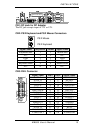
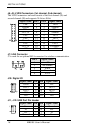
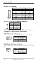
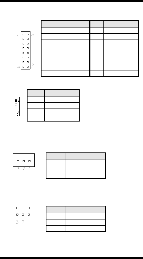
J25: VGA CRT Connector
Signal Name Pin Pin Signal Name
R 1 9 +5V
G 2 10 GND
B 3 11 NC
NC 4 12 DDCDAT
GND 5 13 HSYNC
GND 6 14 VSYNC
GND 7 15 DDCCLK
GND 8 16 TV out
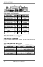
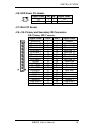
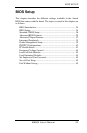
J26: Power Connector (for MB890D / MB890FD)
Pin # Signal Name
1 PS_ON
2 5VSB
3 +3.3V
4 +3.3V
NOTE: MB890D/MB890FD can use the PW53 cable to be able to use
ATX power. J2, J3 and J26 are used for power input.
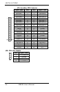
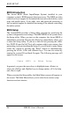
FAN1: CPU Fan Power Connector
FAN1 is a 3-pin header for the CPU fan. The fan must be a 12V fan.
Pin # Signal Name
1 Ground
2 +12V
3 Rotation detection
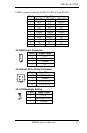
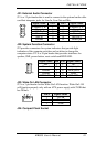
FAN2: System Fan Power Connector
FAN2 is a 3-pin header for system fans. The fan must be a 12V (500mA)
fan.
Pin # Signal Name
1 Ground
2 +12V
3 Rotation detection
22 MB890 User’s Manual