


INSTALLATIONS
MI910 User’s Manual 17
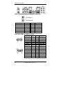
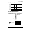
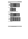
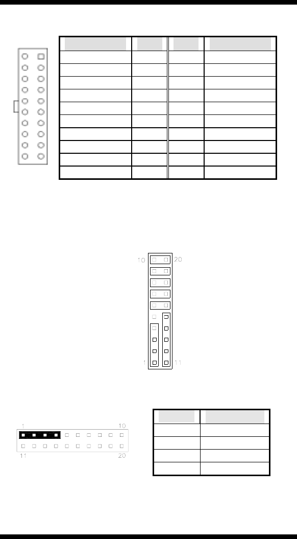
ATX1: ATX Power Supply Connector
Signal Name Pin # Pin # Signal Name
3.3V 11 1 3.3V
-12V 12 2 3.3V
Ground 13 3 Ground
PS-ON 14 4 +5V
Ground 15 5 Ground
Ground 16 6 +5V
Ground 17 7 Ground
-5V 18 8 Power good
+5V 19 9 5VSB
11 1
20 10
+5V 20 10 +12V
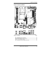
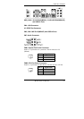
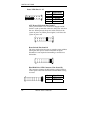
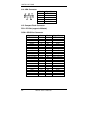
J1 (F_PANEL): System Function Connector
J1 provides connectors for system indicators that provide light indication
of the computer activities and switches to change the computer status. J1
is a 20-pin header that provides interfaces for the following functions.
Hard Disk Drive LED
Reset Switch
Not Defined
ATX Power On Switch
Not Defined
Power LED
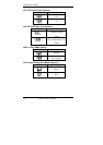
Speaker
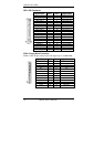
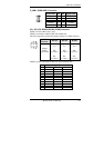
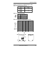
Speaker: Pins 1 - 4
This connector provides an interface to a speaker for audio
tone generation. An 8-ohm speaker is recommended.
Pin # Signal Name
1 Speaker out
2 No connect
3 Ground
4 +5V