


14 Intel® RAID Expander Card RES2SV240 Hardware User’s Guide
— The I2C interface to the external SEP provides a backwards-compatible
interface to an optional external SEP
— All four I2C interfaces can be configured for general-purpose use
— The ARM926 processor can access all four I2C interfaces
• Provides configurable drive spin-up sequencing on a per-phy basis
• Provides programmable Tx and Rx signal polarity for optimization of board routing
• Provides a scalable interface that supports up to 1024 SAS addresses through
multiple expanders
• Offers an advanced LED and GPIO interface that provides serial and parallel GPIO
capabilities:
— Provides a Serial General-Purpose I/O (SGPIO) interface for remote status
indications
— Provides 11 independent GPIO signals
— Provides 72 independent LED signals and two internal port activity indicator
signals that can be used as GPIOs
— Provides LEDs that support drive activity, fault, and status indications
• Provides debug capability via either EPP, Serial, or direct 8-bit CPU interface
• Provides external memory support for Flash, NVRAM and PSBRAM
Flash ROM
An 8-MB CFI-compliant flash ROM is used to accommodate expander card firmware.
Diagnostic Components
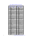
LED Placement and Function
The Intel
®
RAID Expander Card RES2SV240 contains the following LEDs:
• One surface-mounted SXP_ACTIVE (“DS3B1”) LED (Green Color) to indicate
activity of the internal Sxp port operating in any of the supported protocol modes.
• Another surface-mounted EXP_ACTIVE (“DS3B2”) LED (Green Color) to indicate
activity on the internal SMP or SSP target ports which advertise the Expander’s
WWN address.
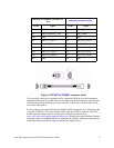
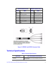
SAS/SATA Connectors
The Intel
®
RAID Expander Card RES2SV240 provides six internal SFF8087 SAS/SATA
signal connectors. Each SFF8087 connector provides support for four SAS/SATA ports.
The sideband signals are configured to adhere to the SFF-8485 Specifications for SGPIO
support.