


3-1
3. Quick Start
This Quick Start Guide describes a simplified installation procedure for the
CMS-6R4 hardware, which will allow you to communicate with the unit in
order to demonstrate basic features and check for proper operation.
Note that this Quick Start Guide does not provide a detailed description of
unit configuration, or discuss advanced operating features in detail. For more
information, please refer to the Installation, Configuration and Operation
sections in this User's Guide.
3.1. Hardware Installation
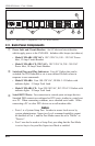
3.1.1. Apply Power to the CMS-6R4
Refer to the safety precautions listed at the beginning of this User's Guide,
and then connect the unit to an appropriate power source. Connect the power
supply cable to the unit’s power inlet, snap the Cable Keeper into place, and
then connect the cable to an appropriate power supply.
Note: The CMS-6R4 is designed for 100 to 120 VAC operation and
the CMS-6R4-CE is designed for 100 to 240 VAC operation.
When power is applied to the CMS-6R4, the ON LED should light, and the
RDY LED should begin to flash. This indicates that the unit is ready to
receive commands.
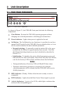
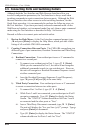
3.1.2. Connect your PC to the CMS-6R4
The CMS-6R4 can either be controlled by a local PC Serial Port, controlled
via modem, or controlled via TCP/IP network. In order to select parameters,
connect ports or control outlets, commands are issued to the CMS-6R4 via
either the Network Port, Modem Port or a Serial RS232 Port.
• Network Port: Connect the CMS-6R4 10Base-T, half duplex network
interface to your network.
• Serial Port: Use the supplied null modem cable to connect your PC
COM port to Serial Port 1 (The System Setup Port.)
• Modem: Connect your telephone line to the CMS-6R4 Phone Line Port.