128-8843
7 of 28
7
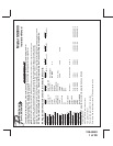
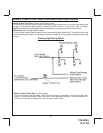
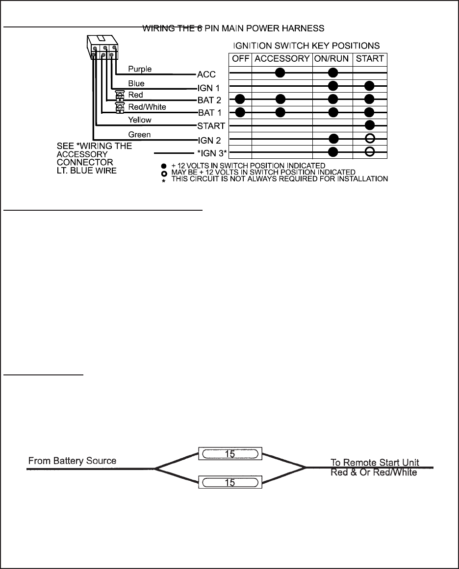
WIRING THE 6 PIN MAIN POWER HARNESS:
WIRING THE 6 PIN MAIN POWER HARNESS:
NOTE: Do not remove the fuse holders from this wire harness. Fuses must be
used and located as close as possible to the power source for ad
equate protection of the vehicle.
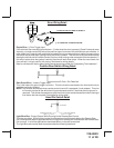
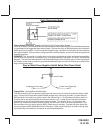
Fused RED w/ WHITE TRACE WIRE: + 12 volt Battery 1 Source
Locate the vehicle battery wire(s) at the ignition switch. Verification: These wires will register voltage in all positions
of the ignition switch. Connect the Red w/White wire to the vehicle's battery wire. This wire provides power for the
control circuit as well as the ignition 1 and ignition 2 relays.
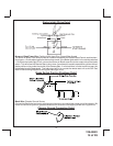
Fused RED WIRE: + 12 Volt Battery 2 Source
Locate the vehicle battery wire(s) at the ignition switch. Verification: These wires will register voltage in all positions
of the ignition switch. Connect the Red wire to the vehicle's battery wire. This wire provides power for the start relay
and the accessory relay.
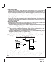
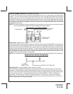
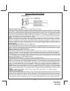
IMPORTANT!
IT IS THE RESPONSIBILITY OF THE INSTALLING TECHNICIAN TO DETERMINE THE LOAD FACTOR OF THE
VEHICLES ELECTRICAL CIRCUITS WHEN THE VEHICLE IS RUNNING AND TO ADEQUATELY FUSE THE TWO
POWER WIRES BASED ON THAT LOAD. IF THE VEHICLE, RUNNING UNDER LOAD WITH THE AIR CONDI-
TIONER, HEATER BLOWER MOTOR AND ACCESSORIES EXCEEDS 24 AMPS CONTINUOUS, WE RECOMMEND
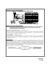
THAT TWO FUSES BE USED IN COMBINATION ON EACH POWER WIRE AS SHOWN BELOW. FOR ADDITIONAL
INFORMATION SEE TECH UPDATE ISSUED 9/30/96.


