7
LSR6328P Biamplified Studio Monitor System
The LSR6328P Bi-amplified Studio Monitor sets the standard for exceptional performance in near field design.
With a combination of advanced transducer engineering and powerful drive electronics, the LSR6328P meets the
professional’s requirement for accuracy and high dynamic range on the most demanding sessions.
The addition of JBL RMC™ Room Mode Correction circuit and boundary compesnation ensures accurate low fre-
quency response at the listening position, free of the spectral shift caused by room modes and the effect of
boundaries.
The 8" woofer is based on JBL's patented Differential Drive
®
technology. With dual 1.5" drive coils, power compression is kept to a
minimum to reduce spectral shift as power levels increase. An added third coil between the drive coils acts as a dynamic brake to limit
excess excursion and reduces audible distortion at maximum levels. The cone is made of a carbon fiber composite forming a rigid pis-
ton and is supported by a soft butyl rubber surround.
The high frequency device is a 1" composite diaphragm integrated with an Elliptical Oblate Spheroidal (EOS) Waveguide with 100° by
60° dispersion, which is critical to the smooth spatial response required in today's working environments. The magnetically sheilding of
the HF transducer reduces interference when used in close proximity to CRT video and computer monitors. This custom power supply
eliminates all tonal-artifacts produced by the speaker when idling.
Audio Connections
LSR6328P Audio Connections:
The LSR6328P comes with a Neutrik "Combi" connector that accommodates either an XLR or 1/4" con-
nector in either balanced or unbalanced configurations. The system has switchable input sensitivity: +4 dBu, +8 dBu, and -10 dBV.
These sensitivities are determined by adjusting the DIP switches according to the legend shown in Figure C. When the sensitivity is set
for, say, +4 dBu, an input signal equal to +4 dBu will produce a system output level of 96 dB SPL at a distance of one meter. Likewise,
settings of +8 dBu and -10 dBV will cause those input levels to attain the output acoustic level of 96 dB SPL.
An additional switch allows user-adjustable input sensitivity via a screwdriver control on the back panel. See Section 4 for additional
information on level control and gain matching. Positive voltage to Pin 2 of the XLR or the tip of the 1/4" jack will produce a forward
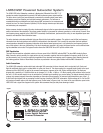
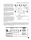
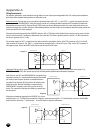
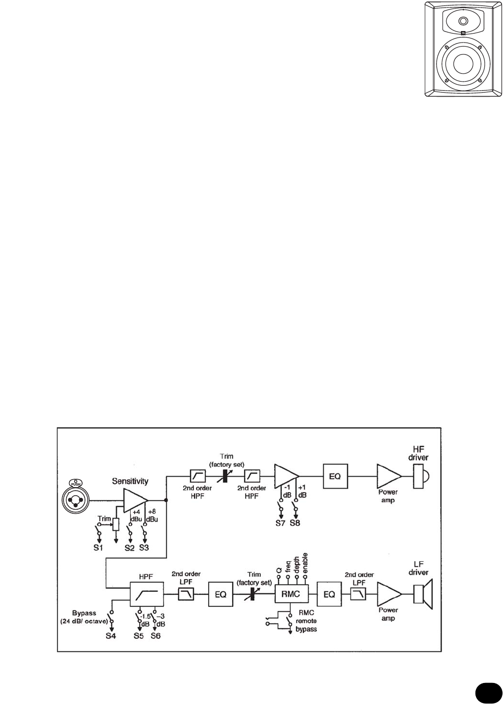
motion in the low frequency cone. Shown below in Figures C and D are views of the rear electronics panel on the LSR6328P and a sig-
nal flow diagram for the system. We recommend that you study these drawings in detail.
Figure D


