


3
10. Connect the Universal Power Supply to AC power.
Note 1: A plug adapter may be required for use outside of North America.
Note 2: In redundant VM installations, remeasure the converter power supply out-
put to be sure it is at 12 volts. This is necessary because of the increased cable load-
ing.
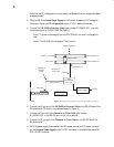
11. The Triton hardware connection is now complete. The Jupiter configuration tables must
be modified to include the Triton switcher. Refer to the Jupiter Facility Control System
Installation and Operating manual, part number 04–045707–002, for information on
configuration for control of Triton switchers.
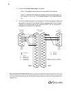
Figure 2. Cables for connecting
VM 3000, Converter, and Triton.
1
6
R–
2
7
3
T–
8
4
9
5
to VM 3000
serial port
G Ground
R– Receive minus
R+ Receive plus
T+ Transmit plus
T– Transmit minus
DB9P
(male)
= twisted pair
T+
R+
G
Tx
DB25S
(female)
1
2
3
4
5
G
6
7
8
9
10
11
12
13
14
15
16
17
18
19
20
21
22
23
24
25
to RS–422/232
converter
1
6
R–
2
7
3
8
4
9
5
DB9P
(male)
T+
Rx
G
to Triton
RS–232 Port
T–
R+
DB25P
(male)
Rx
Tx
G Ground
Rx Receive
Tx Transmit
1
2
3
4
5
G
6
7
8
9
10
11
12
13
14
15
16
17
18
19
20
21
22
23
24
25
©
2003 Thomson Broadcast & Media Solutions, Inc. All rights reserved. All specifications subject to change without notice. GV and
Grass Valley are trademarks of Thomson. For customer service, please call (800) 547–8949. For comments or questions concerning this doc
u-
ment, contact: Technical Publications Department, P.O. Box 30816, Salt Lake City, Utah 84130. Phone: (801) 972–8000. Email: SLCtec
h-
pubs@thmulti.com