


30
Setup for Input Signals
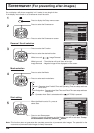
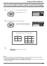
Component / RGB-in Select
Select the input signals to be connected by installing the Optional Video Input Card.
(Refer to the Operating Instructions for the optional Video Input Card.)
Select to match the signals from the source connected to the Component / RGB input terminals.
Y, PB, PR signals
“Component”
R, G, B, HD, VD signals
“RGB”
1
2
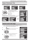
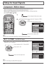
Press to display the Setup menu screen.
Press to select the “Component / RGB-in
Select”.
Press to select the desired input signal.
Press to exit from adjust mode.
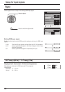
3D Y / C Filter – For NTSC AV images
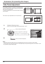
Select “Signal” from the “Setup” menu during AV(S Video) input signal.
(“Signal [AV]” menu is displayed.)
Press to select the “3D Y / C Filter (NTSC)”.
Press to set On / Off.
Press to exit from adjust mode.
Note:
When On, this setting only affects NTSC input signals.
INPUT
SURROUND
VOL
NR
PICTURE
SOUND
SET UP
MULTI
PIP
SWAP SELECT MOVE
ZOOM
Press
(ACTION) button
Component RGB
Setup 1/2
Signal
Screensaver
Input label
Component/RGB-in select
RGB
RGB1
OSD Language
English
(
UK
)
Power save
Off
Standby save
On
Power management
Off
3D Y/C Filter
(
NTSC
)
Colour system
Cinema reality
On
Auto
Off
Aspect Auto
(
4:3
)
4 : 3
Signal
[
AV
]
Setup 1/2
Signal
Screensaver
Input label
Component/RGB-in select
RGB
RGB1
OSD Language
English
(
UK
)
Power save
Off
Standby save
On
Power management
Off
Note:
Selection may not be possible, depending on which optional board is installed.
SET UP
R
R