


7
KV-M65 (EN)
TQBX0223[J]
ENGLISH
ESPAÑOLFRANÇAIS
Introduction to the Roles of the System Components (continued)
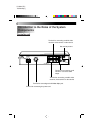
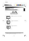
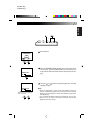
KV-M65 display unit
POWER MODE MENU
Used to display, select and determine the various adjustments
(screen, menu).
Used to turn the power
source ON and OFF
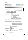
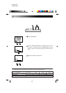
Normally:
Changing the channel setting in the
upward or downward direction
(only when connected to the KV-C1)
When setting various menus:
Menu selection
When setting various adjustment modes:
Adjustment and switching
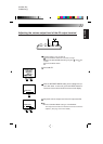
Used to display the configuration screen for changing the input source and the various function menus.
When set to the TV mode, channel numbers are shown. Note, however, that television broad-
cast reception requires connection to the separately sold KV-C1 mobile TV tuner system.
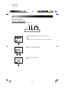
KV-M65
MOBHE COLOR SYSTEMMOBHE COLOR SYSTEM
KV-M65
MOBILE COLOR MONITOR SYSTEM
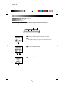
Dimmer sensor
This sensor automatically adjusts the screen brightness. (When
Auto Mode is set for the Dimmer Setting, the screen brightness is
automatically adjusted to one of 12 levels to suit the surrounding
brightness.)
Remote sensor
Used when the JVC mobile TV tuner
system KV-C1 is connected
STAND BY (R), ON (G)
When the power is off ... red
When the power is on ... green
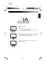
Speaker
(on the back side)
Screw holes are provided for attaching the monitor
stand (on the bottom side).
(1/4 inch unify screw, maximum length of 4.5 mm)
Terminal for connecting
the cable from the
controller unit (on the
right side)
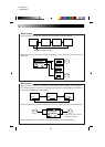
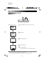
The numbers in the circles ( )
indicate the page on which an
explanation is provided in this manual.