


TM-A101G
1-7
No.51921
ENGLISH
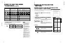
Problems
No power supply.
No picture with the
power on.
No sound.
Shaking picture.
No colors, wrong
color, or dark picture.
Unnatural, irregularly
colored, or distorted
picture.
Dark stripes appear
at the top and bottom
of the screen, picture
vertically squeezed.
Function buttons on
the front panel do not
function.
The INPUT SELECT
buttons do not
function.
Points to be checked
Is the power plug loosened or disconnected?
Is the video signal output from the connected
component?
Is the input signal selected properly?
Is the video cable disconnected?
Is the audio signal output from the connected
component?
Is the volume output set to minimum?
Is the audio cable disconnected?
Is the monitor close to a device generating a
strong magnetic field?
Is the color system selected properly?
Has the picture control setting (CONTRAST,
BRIGHT, CHROMA or PHASE) been changed?
Is the monitor close to a speaker, magnet or any
other device generating a strong magnetic field?
Is the aspect ratio set to 16:9?
Has control of the buttons been locked? (Has
the CONTROL LOCK function been set to ON?)
Is input selection under external control? (Has
the INPUT REMOTE function been set to valid
(A/B)?)
Measures (Remedy)
Firmly insert the power plug.
Set the connected component correctly.
Select the required video signal input with the
Input select button. (See page 7.)
Connect the video signal cable firmly.
(See page 12.)
Set the connected component correctly.
Adjust the speaker volume with the VOLUME/
SELECT button. (See page 7.)
Connect the audio signal cable firmly.
(See page 12.)
Move the device away from the monitor until the
picture stabilizes.
Set COLOR SYSTEM in the <MENU> screen to
AUTO. (See page 8.)
Set each picture control to the standard setting.
(See page 7.)
Move the device away from the monitor and turn
the monitor’s power off. Wait at least 30 minutes,
then turn the power on again.
Set ASPECT RATIO in the <MENU> screen to
[4 : 3 (4 – 3)]. (See page 8.)
When controlling externally, ASPECT RATIO
should be set to [4 : 3 (4 – 3)].
(See page 12.)
Set CONTROL LOCK in the <SET-UP MENU>
screen to OFF. (See pages 9 and 10.)
Set INPUT REMOTE in the <SET-UP MENU>
screen to OFF. (See pages 9 and 10.)
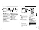
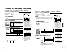
TROUBLESHOOTING
Solutions to common problems related to your monitor are described here. If none of the solutions presented here
solves the problem, unplug the monitor and consult a JVC-authorized dealer or service center for assistance.
The following are not malfunctions:
● When a bright still image (such as a white cloth) is displayed for a long period, it may appear to be colored. This is due to the
structure of the cathode ray tube and will be deleted when another image is displayed.
● You experience a mild electric shock when you touch the picture tube. This phenomenon is due to a normal buildup of static
electricity on the CRT and is not harmful.
● The monitor emits a strange sound when the room temperature changes suddenly. This is only a problem if an abnormality
appears on the screen as well.
● If two or more monitors are operated next to each other, their images may shake or be distorted. This phenomenon is due to
mutual interference; it is not a malfunction. Move the monitors away from each other until the interference disappears or turn
the power off on any monitor that is not being used.
13
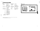
VIDEO A
VIDEO B
AUDIO A
AUDIO B
REMOTE
OUTIN
OUTIN
OUT
OUT
ASPECTINPUT
IN
IN
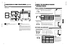
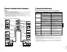
BASIC CONNECTION EXAMPLE
External control switch
Open circuit Closed circuit
(open) (short)
INPUT
INPUT A INPUT B
Notes:
•
Before connecting your system, make sure that all units are turned off.
•
The illustration below shows some examples of different connections. Terminal connections may differ depending on the component connected.
Be sure to refer to the instructions provided with the unit(s) you are connecting.
•
Each pair of input (IN) and output (OUT) terminals are bridge-connected.
•
If you’re not connecting any equipment to a bridged output (OUT) terminal, be sure not to connect any other cables to the bridged output (OUT)
terminal as this will cause the terminating resistance switch to open (auto terminate function).
•
When making a bridge connection, connect the input (IN) and output (OUT) terminals on the monitor to separate video components.
(For example, if both terminals are connected to the same VCR, resonance may occur except during playback. This is caused by the same video
signal “looping” between the VCRs, and is not a malfunction.)
•
Select the video input (INPUT A (VIDEO) or INPUT B (VIDEO)) with the INPUT SELECT buttons on the front panel.
•
The ASPECT RATIO or INPUT A/B settings can be controlled via the REMOTE terminal by setting ASPECT REMOTE or INPUT REMOTE in the
<SET-UP MENU> screen to valid. (Refer to pages 9 and 10.)
Ⅵ VIDEO A Connection Example (Select Input A (VIDEO))
External control
functions
External control switch
closed circuit (short)
open circuit (open)
RCA pin
External control switch
Open circuit Closed circuit
(open) (short)
ASPECT RATIO 4–3 (4:3) 16–9 (16:9)
External control
functions
External control switch
closed circuit (short)
open circuit (open)
RCA pin
Ⅵ VIDEO B (VIDEO) Connection
Example (Select Input B (VIDEO))
Video Camera
Video Monitor
VCR
Video Camera
Video Monitor
VCR
Video
(Video signal cable)
Audio
(Audio signal cable)
Video
(Video signal cable)
Audio
(Audio signal cable)
Audio
(Audio signal cable)
Audio
(Audio signal
cable)
Video
(Video signal cable)
Video
(Video signal cable)
REMOTE
(Remote cable)
REMOTE
(Remote cable)
Video Monitor
VCR
Video Monitor
VCR
12
: Signal Flow