


1-3
TM-A170G
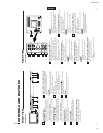
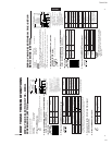
Chroma/Phase button
[
CHROMA/ PHASE]
Press this button to activate the picture color density
adjustment mode or picture hue adjustment mode. Each
time you press the button, the adjustment item changes.
Picture color density
f
Picture hue
Adjust the value with the VOLUME/SELECT buttons
3
.
Also used as a control button in the menu function mode.
Contrast/Brightness button
[CONTRAST
/ BRIGHT ]
Press this button to activate the picture contrast adjust-
ment mode or picture brightness adjustment mode. Each
time you press the button, the adjustment item changes.
Picture contrast
f
Picture brightness
Adjust the value with the VOLUME/SELECT buttons
3
.
Also used as a control button in the menu function mode.
Volume/Select buttons
[VOLUME/SELECT –
+]
Adjusts the speaker volume. Also used as a control
button in the menu function mode.
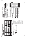
Menu button [MENU]
Displays and disappears the <MENU> screen.
Pressing the CHROMA/PHASE button
1
with the Menu
button depressed will display the <SET-UP MENU>
screen.
Input A (VIDEO) button [INPUT SELECT A]
Selects the video and audio signals input to the VIDEO A
!
and AUDIO A
$
terminals on the rear panel. The
button lights when selected.
CONTROLS AND FEATURES
FRONT VIEW
<Front Panel>
Input B (VIDEO Y/C) button [INPUT SELECT B]
Selects the video and audio signals input to the VIDEO B
@
or VIDEO B (Y/C)
#
and AUDIO B
%
terminals on
the rear panel. The button lights when selected.
Note:
●The VIDEO B terminals include a video terminal (BNC
connector) and a Y/C terminal (mini-DIN 4-pin connec-
tor). The Y/C (S-video) terminal has priority.
Power indicator
Unlit : The main power is OFF.
Orange : The main power is ON, but the monitor’s power
is OFF (in the stand-by mode).
Green : The main power is ON, and the monitor’s power
is ON (in the normal operation mode).
Power switch [POWER ]
Press the power switch to turn the monitor’s power ON or
OFF when the main power is ON.
Speaker
A built-in speaker is located inside the right side panel
when the monitor is viewed from the front.
1
2
3
4
5
6
7
8
9
4
5
7
6
POWER
CHROMA MENU
INPUT SELECT
PHASE
5
0C
BRIGHT
CONTRAST VOLUME/SELECT
AB
8
4
3
21
9
POWER
CHROMA MENU
INPUT SELECT
PHASE
TM-A170
BRIGHT
CONTRASTVOLUME/SELECT
AB
ENGLISH
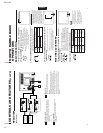
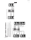
External control terminal [REMOTE]
Remote terminal for external control.
The input signal (the INPUT function) or the aspect ratio
(the ASPECT RATIO function) can be selected by
external control using a switch cable. Setting of the
INPUT REMOTE or ASPECT REMOTE item in the <SET-
UP MENU> screen is required before using external
control.
Refer to the HOW TO USE EXTERNAL CONTROL on
page 14 for more details.
Video A terminals [VIDEO A IN/OUT]
Video signal input (IN) and output (OUT) terminals.
The output terminal is bridge-connected.
IN : Video signal input terminal
OUT : Bridge-connected video signal output terminal
Notes:
*For corresponding audio signals, use the AUDIO A
terminals
$
.
* Also refer to BASIC CONNECTION EXAMPLE
on page 12.
Video B terminals [VIDEO B IN/OUT]
Video signal input (IN) and output (OUT) terminals.
The output terminal is bridge-connected.
IN : Video signal input terminal
OUT : Bridge-connected video signal output terminal
Notes:
*For corresponding audio signals, use the AUDIO B
terminals
%
.
*Also refer to BASIC CONNECTION EXAMPLE on
page 12.
Video B (Y/C) terminals [VIDEO B Y/C IN/OUT]
Y/C (S-video) signal input (IN) and output (OUT) termi-
nals. The output terminal is bridge-connected.
IN :Y/C-separated (S-video) video signal input
terminal
OUT :Bridge-connected Y/C-separated (S-video) signal
output terminal.
REAR VIEW
<Rear Panel>
10
11
12
13
5
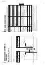
Notes:
* For corresponding audio signals, use the AUDIO B
terminals
%
.
* When both VIDEO B terminals are connected (input) at
the same time, the Y/C terminal has priority.
* Also refer to BASIC CONNECTION EXAMPLE
on page 13.
Audio A terminals [AUDIO A IN/OUT]
Input (IN) and output (OUT) terminals for the audio signal
corresponding to the VIDEO A terminals
!
.
The output terminal is bridge-connected.
IN : Audio signal input terminal
OUT : Bridge-connected audio signal output terminal
Notes:
* For corresponding video signals, use the VIDEO A
terminal
!
.
* Also refer to BASIC CONNECTION EXAMPLE
on page 12.
Audio B terminals [AUDIO B IN/OUT]
Input (IN) and output (OUT) terminals for the audio
signals corresponding to the VIDEO B terminals
@
VIDEO B (Y/C)
#
.
The output terminal is bridge-connected.
IN : Audio signal input terminal
OUT : Bridge-connected audio signal output terminal
Notes:
* For corresponding video signals, use the VIDEO B
terminals
@
or VIDEO B (Y/C) terminals
#
.
* Also refer to BASIC CONNECTION EXAMPLE
on pages 12 and 13.
14
11
10
12
13
14
15
VIDEO A
REMOTE
AUDIO A
AUDIO B
VIDEO B
IN OUT
IN
IN
IN
OUT
OUT
IN
OUT
Y/C
OUT
VIDEO A
AUDIO A
AUDIO B
VIDEO B
IN OUT
IN
IN
IN
OUT
OUT
IN
OUT
Y/C
OUT
15