


ENGLISH
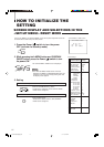
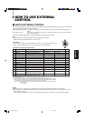
4. To set the other set-up menu items, repeat the
procedures 2 and 3.
5. Press the MENU button to quit.
Notes:
● When the CONTROL LOCK function
is set to ON, pressing operation
buttons on the front panel will display
the message “CONTROL LOCK ON!”
on the screen for about 3 seconds.
● The CONTROL LOCK function is
maintained even when the power is
turned off.
● To turn off the CONTROL LOCK
function, while holding the MENU
button press the CHROMA/PHASE
button. Then set the CONTROL
LOCK function to OFF.
● Even when the CONTROL LOCK
function is set to ON, the following
operations are available:
–Power Switch operation
–Volume control with the VOLUME/
SELECT buttons
– Display or disappear of the <SET-
UP MENU> screen.
● The STATUS DISPLAY function can
be set to display (ON) or not display
(OFF) the present color system when
the power is turned on or the input
signal is changed. Refer to page 7 for
more information.
● When REMOTE SYSTEM is set to
MAKE and any one of the INPUT A
and B buttons or the UNDER SCAN
button is pressed, “REMOTE ON!”
appears on screen for about 3
seconds. (Not shown with CONTROL
LOCK set to ON.)
● When REMOTE SYSTEM is set to
TRG, the front panel controls can be
operated.
● INPUT REMOTE and REMOTE
SYSTEM are enabled when
REMOTE ENABLE is set to ON.
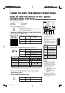
Front panel Function
Contents
button displayed
MENU EXIT
Quit (or Release) the <MENU>
screen
MENU
11
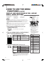
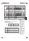
*1 May not be shown depending on the type of signals input.
*2 Refer to HOW TO USE EXTERNAL CONTROL on page 15 for more details.
Note:
Setting Description
MAKE Make contact system: Controls the function using the control
terminal’s short-circuit and open (short-circuits or opens 15th
terminal (GND)).
TRG. Trigger system: Controls the function by short-circuiting (short-
circuits or opens 15th terminal (GND)) with pulse (about 1 sec.)
A-B Switches the input by short-circuiting a specified signal line in
INPUT A or B.
A/B Switches between INPUT A and INPUT B with D-sub pin 2.
Set-up menu items Purpose Settings
PICTURE SUB ADJ. Image sub adjustment Selects CONTRAST/BRIGHT/CHROMA/PHASE. The
selected setting screen is shown. Select the function display for
adjustment.
CONTRAST Adjusts contrast.
BRIGHT Adjusts brightness.
CHROMA Adjusts color density. *1
PHASE Adjusts hue. *1
H. POSITION Adjusts the horizontal position of the
screen (+: Horizontal position shifts
to the right/-: Horizontal position shifts to
the left)
V. POSITION Adjusts the vertical position of the screen
(+: Vertical position moves up/-: Vertical
position moves down)
WHITE BALANCE Adjusts the white balance. Selects the drive (DRV) or cut off (CUTO) adjustment. The selected
setting screen is shown. Select the function display for adjustment.
DRIVE R. DRIVE Adjusts red level.
B. DRIVE Adjusts blue level.
CUT OFF R. CUT OFF Adjusts red cut off.
G. CUT OFF Adjusts green cut off.
B. CUT OFF Adjusts blue cut off.
CONTROL LOCK Sets the operation buttons on the front
panel to control lock mode.
STATUS DISPLAY Sets the status display of the color system.
REMOTE SYSTEM Sets the external control function method. *2
INPUT REMOTE Sets external control of input selection.
(Shown only when REMOTE SYSTEM is *2
set to MAKE.)
–
5 • • •
–
01 00
+
1 • • •
+
5
–
5 • • •
–
01 00
+
1 • • •
+
5
OFF
ON
OFF
ON
MAKE
TRG.
A–B
A/B
–
10
–
9
–
01 00
+
01
+
09
+
10
• •
• •
–
10
–
9
–
01 00
+
01
+
09
+
10
• •
• •
–
10
–
9
–
01 00
+
01
+
09
+
10
• •
• •
–
10
–
9
–
01 00
+
01
+
09
+
10
• •
• •
–
20
–1
9
–
01 00
+
01
+
19
+
20
• •
• •
–
20
–1
9
–
01 00
+
01
+
19
+
20
• •
• •
–
20
–1
9
–
01 00
+
01
+
19
+
20
• •
• •
–
20
–1
9
–
01 00
+
01
+
19
+
20
• •
• •
–
20
–1
9
–
01 00
+
01
+
19
+
20
• •
• •
LCT1092-003A-H[EN]3.p65 07.11.8, 4:49 PM13