


18
HOW TO USE EXTERNAL
CONTROL
Ⅵ ABOUT EXTERNAL CONTROL
This monitor is provided with an external control terminal. MAKE (make contact) or TRIG. (trigger) system can be selected by
the setting of REMOTE SYSTEM in the <SET-UP MENU>.
MAKE (make contact system) : The functino is controlled by short-circuiting or disconnecting each control terminal with pin 15
(GND).
TRG. (trigger system) : The function is controlled by short-circuiting with pulses (for about 1 second) (short-circuit/open
with the 15th pin GND).
* The 14th pin (REMOTE ENABLE) is controlled with MAKE even though TRG. is selected.
* The 1st pin (TALLY) is always controlled by the make contact system regardless of the setting (ON/OFF) of the 14th pin
(REMOTE ENABLE) or the REMOTE SYSTEM setting (MAKE, TRG.) in <SET-UP MENU>.
Note:
● When this monitor is externally controlled, the following buttons are disabled.
MAKE: INPUT-A to D, UNDER SCAN, COLOR OFF, ASPECT on the front panel.
*1 : OFF stands for disconnection, and ON stands for short-circuit.
*2 : When INPUT REMOTE in the <SET-UP MENU> is set to A/B, OFF means “select INPUT A” and ON means “select INPUT B”.
*3 : When INPUT REMOTE in the set-up menu is set to A/B, pins not used should not be connected.
*4 : Do not connect.
*5 : Setting REMOTE ENABLE to ON enables external control from each terminal. (Only TALLY can be externally controlled all the time.)
*6 : INPUT REMOTE setting in the set-up menu (REMOTE SYSTEM shown only when MAKE is selected.)
For the D-sub pins 2, 3, 4 and 5, 4-pin or 1-pin control can be set with INPUT REMOTE in the set-up menu.
• 4-pin control: Switches input by short-circuiting a specified signal line in INPUT A to D.
• 1-pin control: Switches between INPUT-A and INPUT-B only with the 2nd pin of the D-sub connector. In this case, INPUT-C and INPUT-D
cannot be selected.
OFF: INPUT A
ON : INPUT B
NOTES :
* When more than two terminals are selected (short-circuited) from INPUT A through INPUT D under the MAKE system, the signal
input is prioritized alphabetically (A, B, C, D).
* To control INPUT A through INPUT D under the MAKE system, we recommend using the interlock switch, which turns off a
switch when another switch is turned on.
To control INPUT A through INPUT D under the TRG. system, we recommend using the return switch, which stays ON while
pressed.
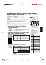
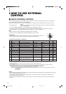
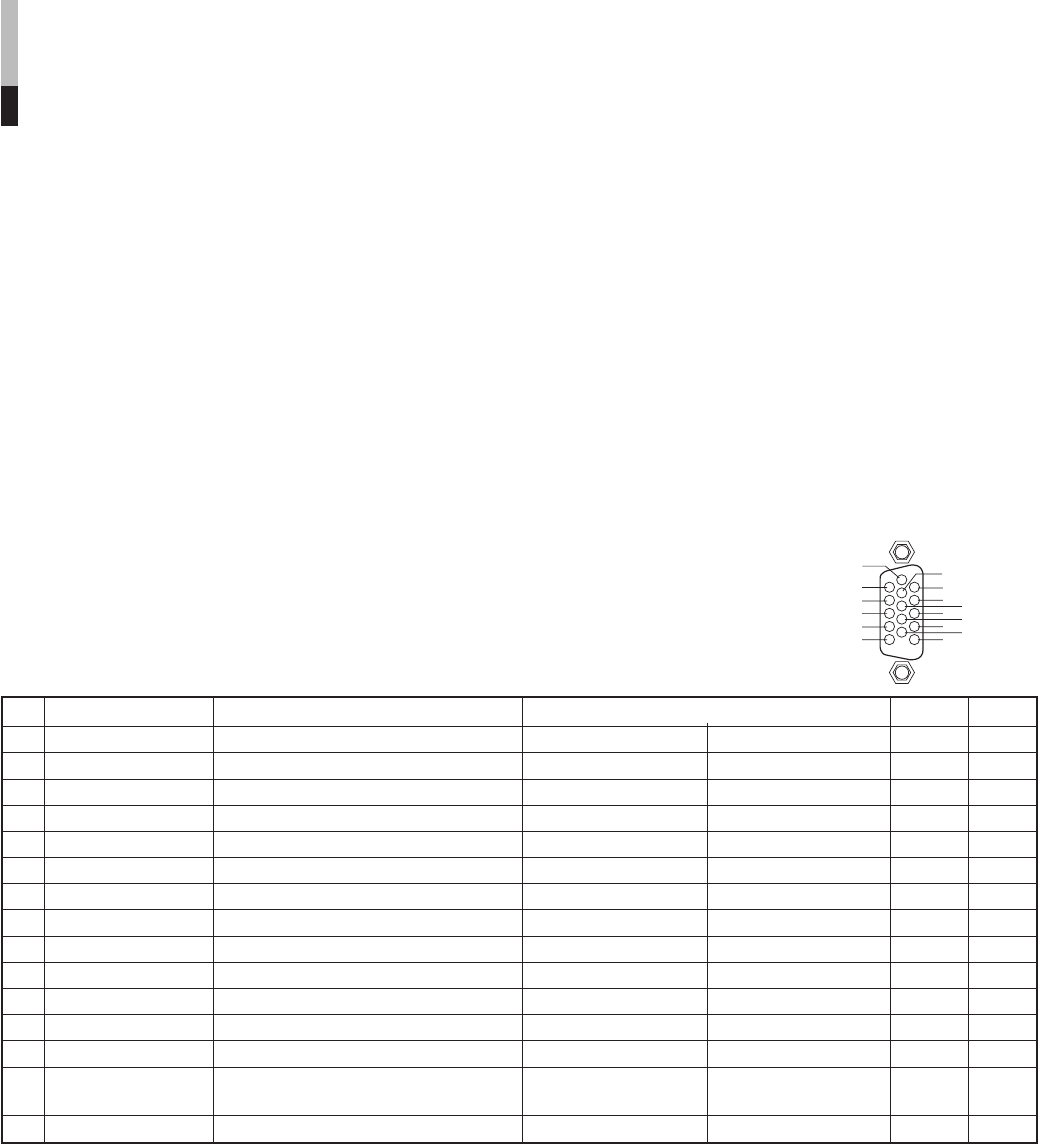
The Names and Functions of Terminals
No. Names Functions Operations (OFF p[ ON) *1
1 TALLY Puts on the tally lamp. Put off Put on
2 INPUT A Changes the input to INPUT A Not change Change *2 *6
3 INPUT B Changes the input to INPUT B Not change Change *3 *6
4 INPUT C Changes the input to INPUT C Not change Change *3 *6
5 INPUT D Changes the input to INPUT D Not change Change *3 *6
6 not used – – – *4
7 not used – – – *4
8 COLOR OFF Changes the picture black-and-white. Not change Change
9 not used – – – *4
10 ASPECT Changes the screen ratio to 16:9 4:3 16:9
11 UNDER SCAN Makes the screen under-scan Over-scan Under-scan
12 not used – – – *4
13 not used – – – *4
14 REMOTE ENABLE Makes the external control from the Invalid Valid *5
REMOTE terminal valid or invalid
15 GND Used as a ground terminal – –
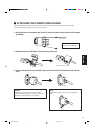
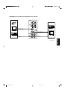
Connections
Connect (short-circuit) the 15th terminal (GND) to each of the 1st through 14th terminals in the
3-lines 15-pins D-sub connector. The functions of each terminal are listed below.
1
2
3
10
8
9
6
7
11
12
13
14
15
4
5
LCT1025-002A-H(EN) 02.4.25, 1:31 PM20