


Preparation
E-5
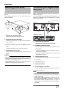
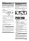
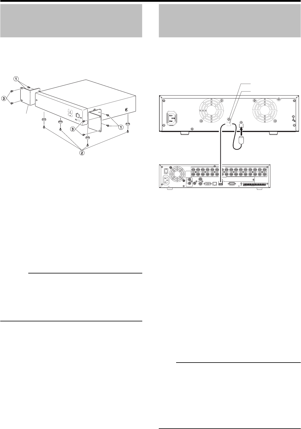
Attaching to the Rack
Use the rack mount fittings provided to attach the unit to the
EIA rack.
When installing this unit in the EIA rack, contact your
nearest JVC dealer.
1. Remove the unit side screws.
Remove the front panel side screws (×4).
2. Attach the rack mount fittings.
Use the four screws (M4 × 10 mm) at ➀ to fasten both
sides of the unit.
3. Remove the feet (×4) from the bottom of the
unit.
Loosen the fastening screws ➁ and remove them.
4. Attach the unit to the rack.
Use the provided four screws (M5 × 11 mm) at ➂ to
fasten.
Caution
• Never place anything on top of a unit with a rack mount
attached. This is to prevent unbalancing the rack, tipping it
over, falling, and damaging the unit.
• When installing two or more units in a rack, leave space
between the units about the size of one unit.
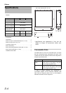
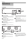
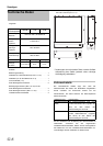
Connecting the Digital Video
Recorder
Before connecting the DVR and this unit, make sure that
both are switched off.
For more details about the settings and operation of the
DVR to be connected to this unit, please refer to the DVR
operating instructions.
1. Connect this unit and DVR.
Use the provided cable to make the connection.
2. Fasten the connection cable.
Be sure to fasten the cable clamp (this prevents cable
disconnection).
➀Loosen the fastener screw of the cable clamp, then
remove the cable clamp.
➁Pass the connection cable through the cable clamp
then fasten it to the unit.
3. Connect the power cord.
Connect the power cord plug to an AC 120 V - 240 V
power outlet.
4. Switch this unit on.
5. Switch the DVR on.
6. Do the settings for the DVR.
Do the settings by following the procedures in the DVR
operating instructions.
Note
• Never switch off the unit while the HDD ACCESS display is lit.
• Always make sure that the DVR is switched off before you
switch on this power.
• Always power off the DVR before you switch off this unit.
(The HDD ACCESS display may stay lit for about 30
seconds after the DVR has been turned off. You may turn
off the power to the equipment because communication
has ended.)
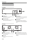
Rack mount
fitting
POWER
ON
OFF
AC IN 100V
2345 78910111213
14 15 16
6
1
2
2
2
3 4 5 7 8 9 10 11 12 13
14 15 16
6
1
1
1
VIDEO IN
THROUGH OUT
SPOT OUT
VIDEO OUTAUDIO OUTAUDIO IN VGA OUT LAN SERIAL
SIGNAL
GND
RS-232C
ALARM IN
1
2
3
4
5
6
7
8
9
10
11
12
13
14
15
16
COMMON
EMERGENCY
CLOCK RESET IN
CLOCK RESET OUT
ALARM RESET
REC OUT
COMMON
COMMON
COMMON
WARNING OUT
EXT REC IN
OPE ON/OFF
SPOT 1
SPOT 2
RESERVE 1
RESERVE 2
AC IN
TO RECORDER
VR-D0U
Digital video recorder
Cable clamp fastener screw
Cable clamp
To the serial terminal
Connection cable (provided)