


Options
ADS#44507 Printed in USA
KCT-34
Interface Cable
(for TK-780/880
980/981 mobiles)
KCT-40
Interface Cable
(for TK-7180/8180
7150/8150 mobiles)
KGP-2B GPS CONTROLLER-MODEM
Main Data TX Commands
◗Single Call ◗Multiple Call ◗Group Call ◗Auto Data TX
Request ◗District Call ◗Emergency ◗Input Data Request
(I/IO input ports; contact closures,sensors, etc.)
Main Mobile Station Settings
◗Outputs Data Request (I/O ports outputs) ◗GPS Data
Mobile Station
Base Station
KCT-35
Interface Cable
(for 60G/62G-Series mobiles)
*1
KCT-36
Extension Cable
(for KCT-34/35/40)
*1
160G/62G-Series Mobiles:TK-760G/762G/860G/862G/768G/868G/863G except for European models
Not all accessories may be available, please contact dealers for details.
Applicable MIL-STD
Military Standard Method / Procedure Method / Procedure Method / Procedure
810C 810D 810E
Dust 510.1/Proc. 1 510.2/Proc. 1 510.3/Proc. 1
Vibration 514.2/Proc. 8,10 514.3/Proc. 1 Cat.8 514.4/Proc. 1 Cat.8
Shock 516.2/Proc. 1,2,5 516.3/Proc. 1,4 516.4/Proc. 1,4
Specifications
General Specification
Dimensions (W x H x D) without projections 5.51 x 1.81 x 3.94 in (140 x 46 x 100mm)
Weight: KGP-2A 1.01 lbs (460 g)
KGP-2B 0.93 lbs (420 g)
Standard Input Voltage DC 13.6V negative ground
(Input Voltage Range) (DC 10.0V to 15.7V)
Temperature Range -22°F to + 140°F (-30°C to + 60°C)
Current Drain < 300 mA (KGP-2A) , < 240 mA (KGP-2B)
GPS Receiver Unit (applies to KGP-2A only)
Receiver Type Parallel 9 channels
Receiver Frequency 1,575.42 MHz
Supply Voltage to Antenna DC 3.3V ± 0.2 V
GPS Backup Term More than 2 month (fully charged)
Modem
Modulation Minimum shift keying (MSK)
Modulation Rate 1,200 / 2,400 bps
Modem Encode Level Range 100 ~ 1,000 mVrms
Modem Decode Level Range 100 ~ 1,000 mVrms
Input Impedance 600 Ω
Output Impedance 600 Ω
JQA-QMA1205
❚ MIL-STD Environmental Standards
Compliance with MIL-STD 810 C/D/E environmental
standards for resistance to dust,vibration and shock
ensures stable performance even in demanding conditions.
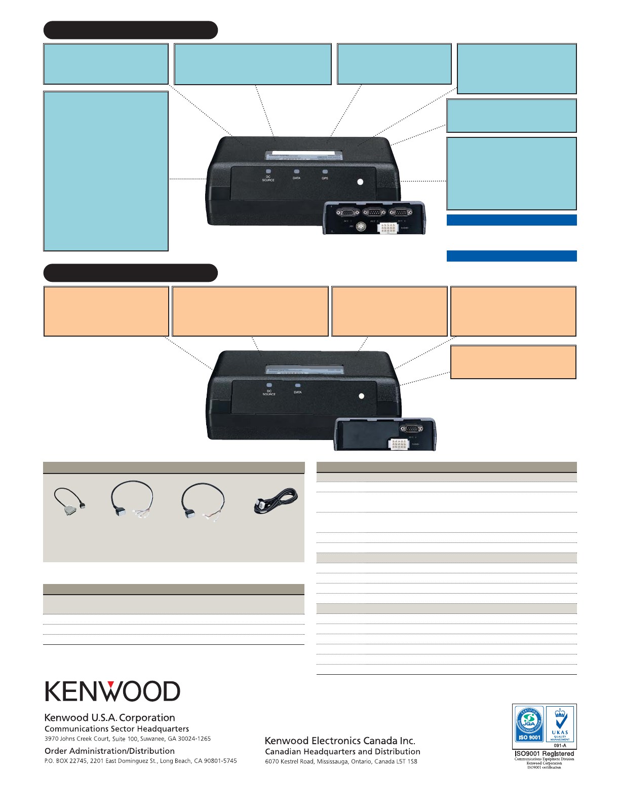
KGP-2A GPS RECEIVER-MODEM
❚
Compact Lightweight Design
Measuring just 5.51 x 1.81 x 3.94 inches
(W x H x D) and weighing 1.01 pounds,the
KGP-2A can be easily installed in any vehicle.
❚
Flash Memory
Flash memory permits uploading KGP-2A/2B
unit firmware upgrades with a computer.
❚
LED Status Indicators
LEDs provide a quick troubleshooting indica-
tor to confirm DC power,data communica-
tions with the connected mobile radio or if
a GPS signal is being received.
❚
Compact Lightweight Design
Measuring just 5.51 x 1.81 x 3.94 inches
(W x H x D) and weighing 0.93 pounds,
the KGP-2B can be easily installed out of
the way base installation.
❚
DSP Modem
The receiver features a modern DSP-type
modem (Digital Signal Processor) capable
of 1200/2400 bps data communications.
❚
DSP Modem
The receiver features a modern DSP-type
modem (Digital Signal Processor) capable
of 1200/2400 bps data communications.
Kenwood follows the policy of continuous advancement in development.
For this reason specifications may be changed without notice.
❚
MIL-STD Environmental Standards
Compliance with MIL-STD 810 C/D/E environmental stan-
dards for resistance to dust,vibration and shock ensures
stable performance even in demanding conditions.
rear panel
rear panel
❚
Multi-purpose
Programmable I/O’s
Each KGP-2A has sixteen programmable
I/O’s for either an analog “input” or output”
[available at external connectors ACC2
(DB-9) & ACC-3 (DB-15)].The inputs are
useful for vehicular sensors,switches,
contacts,etc. and generate a report to the
KGP-2B base unit each time the status
changes*.The outputs can be used to trigger
external relays and controls*.A KGP-2B base
unit can be commanded by a control/base
station computer running a KGP-2A/2B AVL
dispatcher application to activate/deactivate
KGP-2A fleet unit outputs and/or poll current
input/output status.
* Requires additional circuitry and added parts; also requires
a KGP-2A/B compatible AVL/dispatch software
capable of utilizing these I/O’s.
❚
Flash Memory
Flash memory permits uploading KGP-2A/2B
unit firmware upgrades with a computer.
❚
Control
The KGP-2A/2B air protocol commands permit
a KGP-2B base unit to request any KGP-2A
fleet unit to send any currently stored data or
mobile station settings.AVL mapping / dispatch
CAD software developers are provided with
these commands and all protocol information
to utilize in their products.
❚
LED Status Indicators
LEDs provide a quick troubleshooting
indicator to confirm DC power,data commu-
nications with the connected mobile radio.