


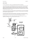
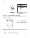
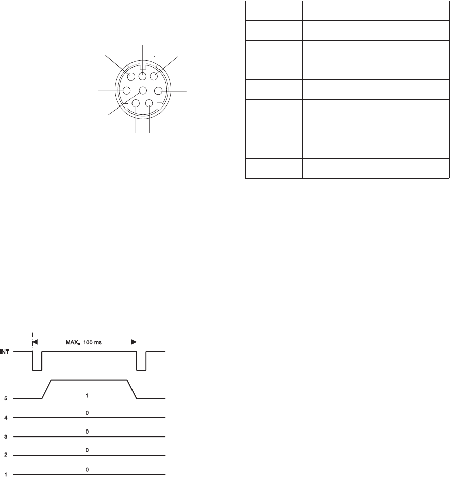
Remote Control
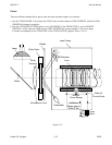
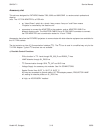
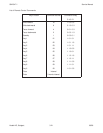
Pin No.
Signal
1
12 VDC
2
Gnd
3
Signal 1 (LSB)
4
Signal 2
5
Signal 3
6
Signal 4
7
Signal 5 (MSB)
8
Interrupt
12 VDC = average value between
7.2VDCand14.5VDC
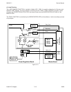
Because of the microprocessor, the REMOTE CONTROL also works with digital signals on the TTL level.
RANDOM ACCESS is also available through a REMOTE CONTROL receptacle.
The data is sent parallel as a 5 bit code from the CABLE REMOTE or the IR RECEIVER to the projector
(Keyboard PCB) with an interrupt signal.
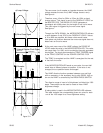
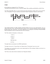
The example shows the binary code
10000.The code 10000 is for FORWARD.
When a button on the REMOTE CONTROL
is pressed, the INT signal is low with a
maximum value of 1 µ s. Then it becomes
high again. After that the data transmission
begins.
While the focus and tray motion signal consist of only one 5 bit data record. The slide position values are always
sent as three successive 5 bit data.
For example:
Slide No. 3 = decimal 20 20 23 , binary 10100 10100 10111
Slide No. 140 = decimal 21 24 20 , binary 10101 11000 10100
figure 3-15
5
1
2
3
4
6
7
8
Type Mini DIN
(
viewed from front
)
figure 3-16
Service Manual SM 2547-1
03/98 3-20 Kodak AG, Stuttgart