


For i280, 3590C and i600/i1800 (without
image addressing) Series Scanners
The minimum overall length of the patch bars is
0.75 inches (19 mm).
Patch Positioning
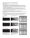
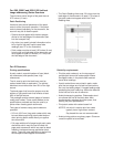
Horizontal and vertical placement of the patch
code is critical for proper operation. If the patch
code is placed improperly on the document, the
scanner may fail to read the patch.
• Patches should appear with the bars perpen-
dicular to the lead edge of the document (fed
into the transport first).
• Any other (non-patch) printed information to the
left or right of the patch could cause false
readings (see “E” on the illustration).
• Patch codes must be at least 0.25 inches (6 mm)
from the left and right edge of the document and
must appear at least 0.5 inches (12.7 mm) from
the lead edge of the document.
For All Scanners
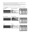
Printing specifications
A patch code is a parallel pattern of bars (black,
low reflectance) and spaces (clear, high
reflectance).
The ink used to print the black bars must be
carbon-based black or equivalent. The printed
black bars must reflect less than 20% of the light
source.
The bond paper that forms the spaces must be
white or a light pastel color that reflects at least
65% of the light source.
This package contains several pages of camera-
ready patch codes. These copies adhere to the
specifications provided and may be used by a
printer when creating patch documents.
Two types of camera-ready patch codes are
provided:
• 2.5-inch (62.5 mm) long patch codes which may
be used when preprinting patch code labels or
when printing patch codes directly on applica-
tion documents.
• Full-page width and full-page length patch code
documents which may be used to create full-
page patch documents which are used as batch
headers; interleaved among application docu-
ments. These full-page patches may be fed into
the transport without regard to orientation.
Reliability requirements
• Print the patch code only on the top page of
multiple-part forms with carbon paper inserts.
Smudged carbon in the patch code area can
cause false readings.
• If patch-coded forms are printed in pads, make
sure the torn edges are not fed into the machine
first (not the leading edge). A ragged leading edge
preceding the patch code may cause the distance
to the first bar to be out of tolerance.
• Avoid photocopying patches. Photocopiers tend
to increase the size of the black bars while
simultaneously reducing the white space, thus
altering the print specifications.
• Print patch codes with carbon-based ink.
NOTES: Ink which is used to print bar codes
typically has a high carbon content.
Soy-based inks are not recommended.
• Avoid printing patches on glossy paper. Glare can
cause the patch to be misread.
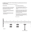
• The Patch Reading Area ends 2.0 inches from the
lead edge of the document. At least 0.75 inches of
the patch code must appear within the Patch
Reading Area.