


16
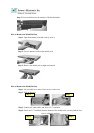
1.5 FW-7650 19” 1U Rackmount Firewall Mechanisms
This section of the manual describes the mechanical and device nomenclature of FW-7650.
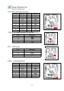
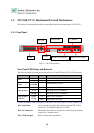
1.5.1 Face Panel
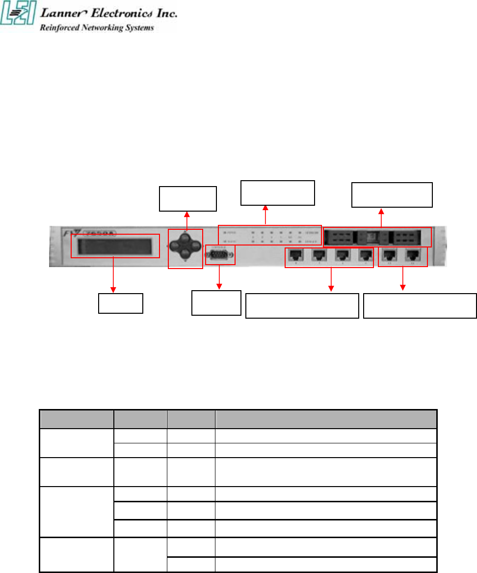
Figure 5 – FW-7650 Face Panel
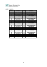
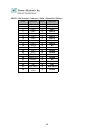
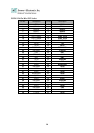
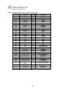
Face Panel LED Status and Behavior
The following table lists and explains the behavior of each LED on the FW-7650 front panel.
LED Color Status Description
Green On When FW-7650 power is switched ON
PWR
N/A Off No power connected
Status Green/Red
Programmable via GPIO
N/A The speed of LAN is 10Mbit/s
Green
The speed of LAN is 100Mbit/s
Ethernet Ports
Orange The speed of LAN is 1000Mbit/s
On When LAN is connected
Ethernet Ports
Link/ACT
Green
Orange
Flash When Data is accessing
Lanner provide the LED status sample in the path //FW-7650_MB-X71/ LED_Sample_Code
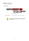
Console Port: via the console port cable, this connector attaches FW-7650 to
the host PC. The Default baud rate is 115200.
LAN Connector: Ethernet RJ-45 connector, connected to networking environment
using a RJ-45 Ethernet cable
LCM & Keypad Please reference the Appendix B
LCM
Key PAD
Console
LED Indicator
2.5” Hdd Bay
10/100 LAN Connector Gigabit LAN Connector