


Appendix B
Watchdog Timer
Introduction
Most systems need to be self-reliant. It's not usually possible to wait for someone to reboot them
if there are some component wrong. Some system designs, such as space probes, are simply not
accessible to human operators. If the system ever hangs, such systems are permanently disabled.
In other cases, the speed with which a human operator might reset the system would be too slow
to meet the uptime requirements of the product.
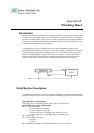
A watchdog timer is a piece of hardware that can be used to automatically detect system
anomalies and reset the processor if any occur. Generally speaking, a watchdog timer is based on
a counter that counts down from some initial value to zero. The software selects the counter's
initial value and periodically restarts it. If the counter ever reaches zero before the software
restarts it, the software is presumed to be malfunctioning and the processor's reset signal is
asserted. The processor will be restarted as if a human operator had cycled the power.
Detail Register Descriptions
A watchdog action consists of a series of watchdog instructions. A watchdog instruction is the
operation on a register region. This section describes the detail register in LPC I/O(W83627HF).
Watch Dog Timer Control Register
Watch Dog Timer is controlled by CRF5, CRF6, CRF7 of Logical Device.
CRF5 (PLED mode register. Default 0x00)
Bit 7-6 : select PLED mode
= 00 Power LED pin is tri-stated.
= 01 Power LED pin is drived low.
= 10 Power LED pin is a 1Hz toggle pulse with 50 duty cycle
= 11 Power LED pin is a 1/4Hz toggle pulse with 50 duty cycle.
Bit 5-4 : Reserved
Bit 3 : select WDTO count mode.
= 0 second
= 1 minute
Bit 2 : Enable the rising edge of keyboard Reset(P20) to force Time-out event.