


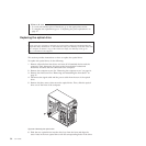
v If the voltage supply range in your local country or region is 200–240 V ac,
set the voltage-selection switch to 230 V.
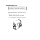
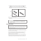
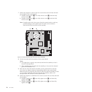
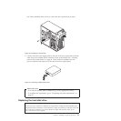
7. Install the new power supply assembly into the chassis so that the screw holes
in the new power supply assembly are aligned with the corresponding holes in
the rear of the chassis.
8. Install the four screws to secure the new power supply assembly in place.
Note: Use only screws provided by Lenovo.
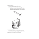
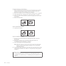
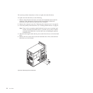
9. Connect the new power supply assembly cables to all drives and the system
board. See “Locating parts on the system board” on page 11.
What to do next:
v To work with another piece of hardware, go to the appropriate section.
v To complete the replacement, go to “Completing the parts replacement” on
page 37.
Replacing the heat sink and fan assembly
Attention
Do not open your computer or attempt any repair before reading and understanding the
“Important safety information” in the ThinkCentre Safety and Warranty Guide that came with
your computer. To obtain a copy of the ThinkCentre Safety and Warranty Guide,goto:
http://www.lenovo.com/support
This section provides instructions on how to replace the heat sink and fan
assembly.
CAUTION:
The heat sink and fan assembly might be very hot. Turn off the computer and
wait three to five minutes to let the computer cool before removing the
computer cover.
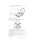
To replace the heat sink and fan assembly, do the following:
1. Remove all media from the drives and turn off all attached devices and the
computer. Then, disconnect all power cords from electrical outlets and
disconnect all cables that are connected to the computer.
2. Remove the computer cover. See “Removing the computer cover” on page 14.
3. Lay the computer on its side for easier access to the system board.
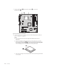
4. Locate the heat sink and fan assembly. See “Locating components” on page 10.
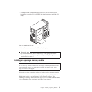
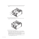
5. Disconnect any cables that might prevent your access to the heat sink and fan
assembly.
6. Disconnect the heat sink and fan assembly cable from the microprocessor fan
connector on the system board. See “Locating parts on the system board” on
page 11.
Chapter 2. Installing or replacing hardware 25