


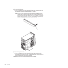
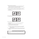
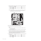
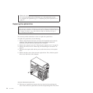
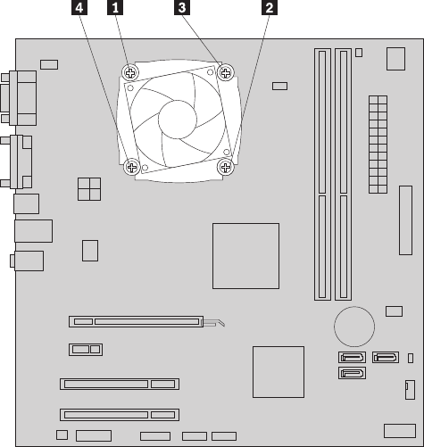
7. Follow this sequence to remove the four screws that secure the heat sink and
fan assembly to the system board:
a. Partially remove screw 1, then fully remove screw 2, and then fully
remove screw 1.
b. Partially remove screw 3, then fully remove screw 4, and then fully
remove screw 3.
Note: Carefully remove the four screws from the system board to avoid any
possible damage to the system board. The four screws cannot be
removed from the heat sink and fan assembly.
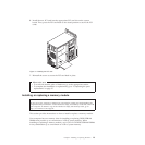
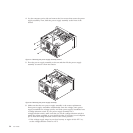
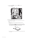
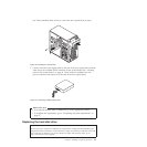
8. Lift the heat sink and fan assembly off the system board.
Notes:
a. You might have to gently twist the heat sink and fan assembly to free it
from the microprocessor.
b. When handling the heat sink and fan assembly, do not touch the thermal
grease on the bottom of it.
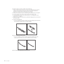
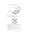
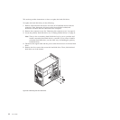
9. Place the new heat sink and fan assembly on the system board so that the
four screws are aligned with the corresponding holes in the system board.
Make sure that you properly place the new heat sink and fan assembly so that
you can easily connect the new heat sink and fan assembly cable to the
microprocessor fan connector on the system board.
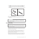
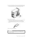
10. Follow this sequence to install the four screws to secure the new heat sink and
fan assembly:
a. Partially tighten screw 1, then fully tighten screw 2, and then fully
tighten screw 1.
b. Partially tighten screw 3, then fully tighten screw 4, and then fully
tighten screw 3.
Figure 19. Screws that secure the heat sink and fan assembly
26 User Guide