


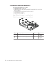
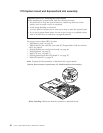


1170 System board and ExpressCard slot assembly
For access, remove these FRUs in order:
v “1010 Battery pack” on page 54
v “1090 Wireless LAN card slot cover and PCI Express Mini Card for wireless
LAN” on page 65
v “1110 Keyboard cover and power board” on page 68
v “1130 Keyboard” on page 71
v “1140 LCD unit” on page 73
v “1150 Keyboard bezel and LED board L” on page 76
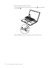
v “1160 LED board R” on page 79
Note:
ExpressCard slot assembly is attached to the system board.
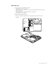
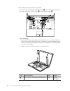
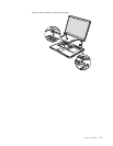
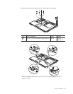
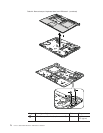
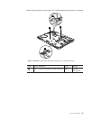
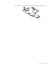
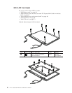
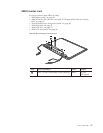
Table 26. Removal steps of system board, PC Card/ExpressCard slots assembly
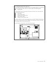
1
When installing: Make sure that the connector is attached firmly.
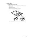
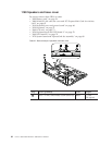
Important notices for handling the system board:
When
handling the system board, bear the following in mind.
v Be careful not to drop the system board on a bench top that has a hard
surface, such as metal, wood, or composite.
v Avoid rough handling of any kind.
v At every point in the process, be sure not to drop or stack the system board.
v If you put a system board down, be sure to put it only on a padded surface
such as an ESD mat or conductive corrugated material.
80 Lenovo 3000 N500 Hardware Maintenance Manual