


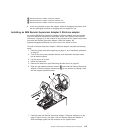
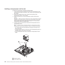
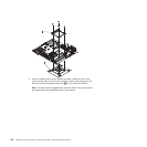
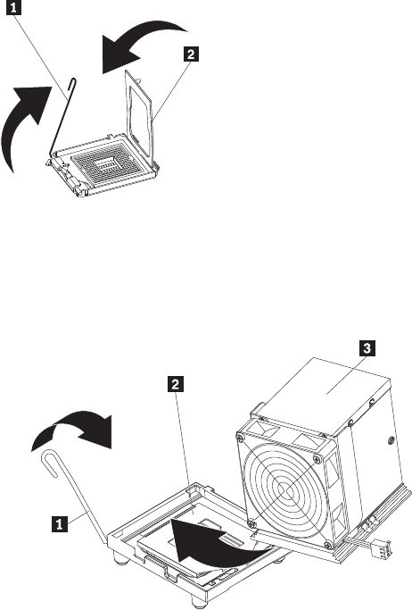
5. Close the microprocessor bracket frame 2; then, close the microprocessor
retention latch 1 and lock it securely in place.
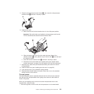
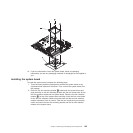
6. Install the fan sink:
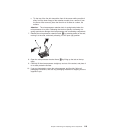
a. Make sure that the fan-sink retention lever is in the fully open position.
Important: Be careful when you handle the microprocessor and fan sink.
Do not contaminate the thermal material between them.
b. Slide the bottom edge of the fan sink under the lower flange of the
retention module 2; then, place the top of the fan sink 3 onto the top of
the retention module.
c. Close the fan-sink retention lever 1 and lock it securely in place.
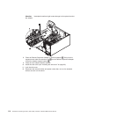
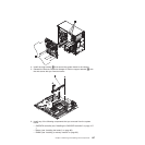
d. Reconnect the fan-sink cable to the system board (see “System board
internal connectors” on page 10 for the location of the fan-sink connector).
7. Reconnect any cables that you disconnected during the removal of the old
microprocessor.
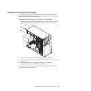
8. Install the side cover (see “Installing the side cover” on page 63).
9. Lock the side cover if you unlocked it during removal.
10. Reconnect the external cables and power cords; then, turn on the attached
devices and turn on the server.
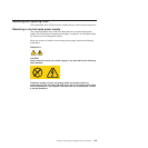
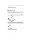
Thermal grease
The thermal grease must be replaced whenever the fan sink has been removed
from the top of the microprocessor and is going to be reused or when debris is
found in the grease.
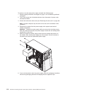
When you are installing the fan sink on the same microprocessor that is was
removed from, make sure that:
v The thermal grease on the fan sink and microprocessor is not contaminated.
Chapter 4. Removing and replacing server components 121