


6. Restart the computer, leave it on for approximately ten seconds. Turn off the
computer by holding the power switch for approximately five seconds. The
computer will turn off.
7. Repeat steps 1 through 3 on page 30.
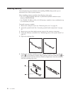
8. Move the Clear CMOS/Recovery jumper back to the standard position (pins 1
and 2).
Note: If your system board has only two pins for clearing CMOS, just remove
the jumper from the two pins.
9. Replace the computer cover and connect the power cord. See “Replacing the
cover and connecting the cables.”
Replacing the cover and connecting the cables
After working with options, you need to install any removed parts, close the
computer cover, and reconnect cables, including telephone lines and power cords.
Also, depending on the option that is installed, you might need to confirm the
updated information in the Setup Utility program.
To replace the computer cover and connect cables to your computer:
1. Ensure that all components have been reassembled correctly and that no tools
or loose screws are left inside your computer.
2. Reposition any cables that might impede the replacement of the computer
cover.
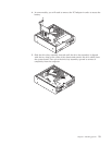
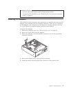
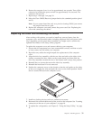
3. Align the drive bay assembly with the two slots and rails on the sides of the
chassis, reconnect the drive cables on the system board, and then slide the
drive bay assembly towards the rear of the chassis until it snaps into position.
4. Reinstall the two screws that secure the drive bay assembly.
5. Reinstall the front bezel if it was removed.
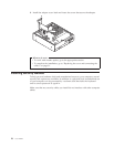
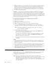
6. Position the computer cover on the chassis so that the rail guides on the sides
of the cover engage the rails and push the cover to the closed position. Install
the two screws that secure the computer cover.
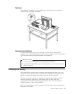
7. Install any locking devices such as a padlock as necessary.
8. Reconnect the external cables and power cords to the computer. See “Locating
connectors on the rear of your computer” on page 18.
9. To update the configuration, see Chapter 5, “Using the Setup Utility,” on page
41.
Chapter 3. Installing options 31