


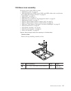
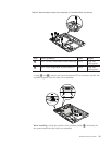

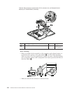
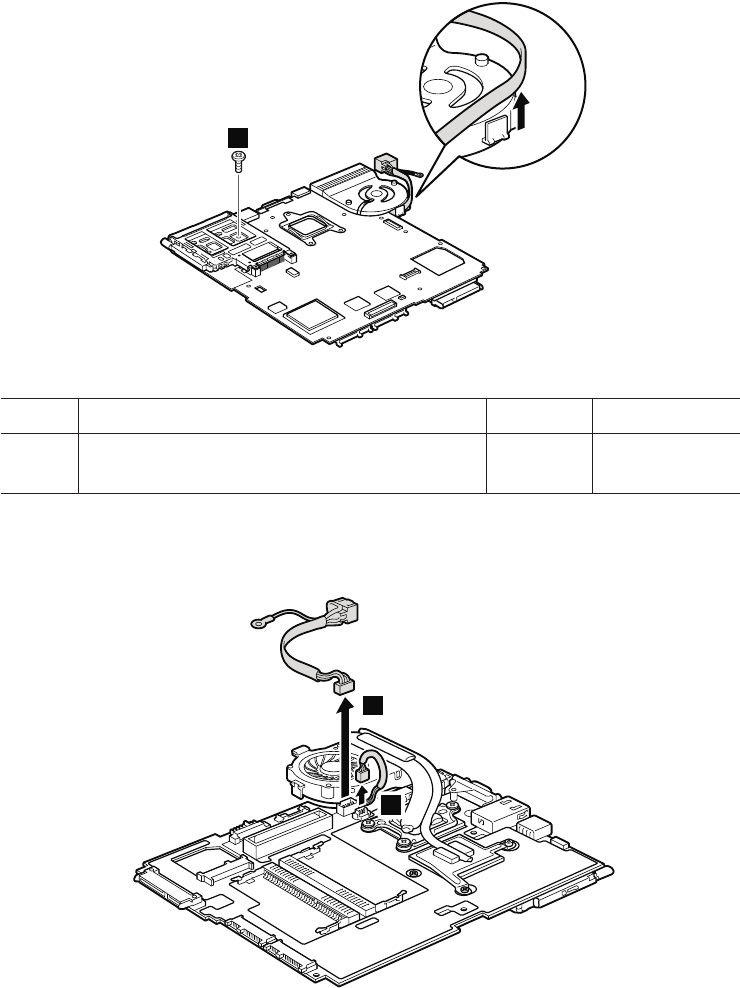
Table 26. Removal steps of system board, DC-in connector, fan, and ExpressCard slot
assembly for ThinkPad X200 (continued)
Note: The DC-in connector and the fan assembly are attached to the underside
of the system board.
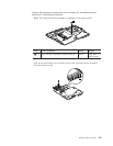
1
Step Screw (quantity) Color Torque
1 M2 × 3.5 mm, wafer-head, nylon-coated (1) Silver 0.181 Nm
(1.85
kgfcm)
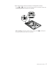
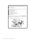
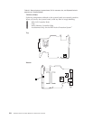
Turn the system board over, and then disconnect the DC-in connector and the
fan connector from the system board.
2
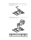
3
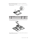
When installing: Make sure that the DC-in connector and the fan connector are
attached to the system board firmly.
ThinkPad X200 and X200s 103