


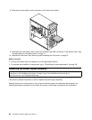
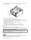
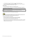
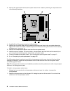
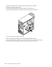

10. Remove the eight screws that secure the system board to the chassis by following the sequence shown
in the following illustration.
11. Carefully lift the failing system board out of the chassis.
12. Position the new system board into the chassis so that the screw holes in the new system board are
aligned with those in the chassis. Install the eight screws that secure the system board to the chassis by
installing screw 8 to screw 1 .
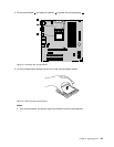
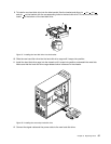
13. Remove the microprocessor socket cover from the new system board.
14. Install the memory modules, PCI cards, battery, microprocessor, and heat sink and fan assembly that
you removed from the failing system board to the new system board.
15. Connect all cables to the system board. See “Locating parts on the system board” on page 71.
16. Go to “Completing the parts replacement” on page 102.
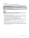
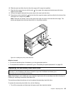
The failing system board must be returned with microprocessor socket covers to protect the pins during
shipping and handling. Install the microprocessor socket covers removed from the new system board
on the failing system board.
Note: The microprocessor socket cover installation procedure should be performed on both microprocessor
sockets on the failing system board.
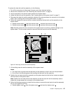
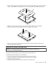
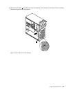
To install a microprocessor socket cover:
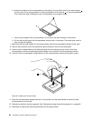
1. Release the lever securing the microprocessor retainer and open the retainer to access the
microprocessor.
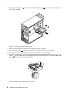
2. Grasp the microprocessor on the sides and lift it straight up and out of the socket. Do not touch the
contacts on the microprocessor socket.
92 ThinkStation Hardware Maintenance Manual