


11. Lower the handle until it is fully in the down position and locked into the
socket. This secures the microprocessor in the socket.
12. Remove the cleaning pad from its package and use the cleaning pad to wipe
the thermal grease from the bottom of the heat sink.
Notes:
a. The cleaning pad and thermal grease are separate FRUs and are not
included with the system board or microprocessor FRUs. These must be
ordered separately and shipped along with the FRUs being replaced.
b. Be sure that all of the thermal grease is removed.
Note:
0.01ML is one tick mark on the syringe. If the grease is properly
applied, approximately half (0.22ML) of the grease will remain in the
syringe.
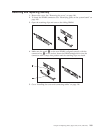
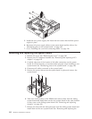
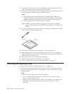
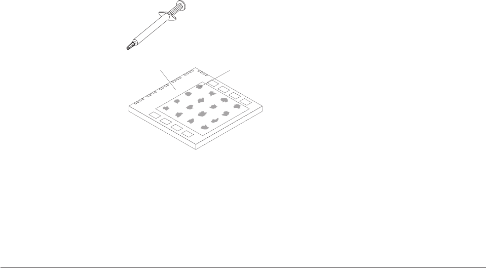
13. Use the thermal grease syringe to place 16 uniformly spaced dots of 0.01ML
each on the top of the microprocessor.
Microprocessor
0.01 mL of
thermal grease
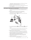
14. Place the fan and heat sink into position on the microprocessor.
15. When tightening the screws that clamp the heat sink, do not overtighten.
Tighten the clamp screws evenly by tightening one side some and then the
other until they are both snug.
16. Reconnect the fan to the system board connector.
17. Replace any air baffles or ducts that were removed.
18. Go to “Installing the cover and connecting cables” on page 116.
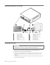
Removing and replacing drives
1. Remove the cover. See “Removing the cover” on page 106.
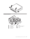
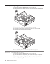
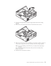
2. Pivot the drive-bay latch handle toward the front of the computer and then
pivot the appropriate drive-bay cage upward, as shown, until latched in the
upright position.
Notes:
a. Both drive-bay cages pivot in the same manner.
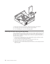
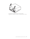
b. You can lift the drive-bay cages out of the chassis to make it easier to
remove and install the drives.
c. Take note of the location of any cables you disconnect. You might have to
disconnect cables to other drives to gain access to the drive you are
removing.
114 Hardware Maintenance Manual